Build Part 4
Note
I won't change this page, as it still shows what I did in my original setup. This info is still good info as everything I did here worked just fine. But, I have now successfully moved my Throttle Body to be upstream of the Supercharger. As a result, a large portion of this page is no longer relevant. No more need of a CBV for example. Also, all the various Silicon couplers and elbows have become an issue. This is because with the moved TB, these parts now see both full Vaccum as well as boost. Silicon couplers just can't stand up to 20inHg of vacuum without collapsing.
So, please feel free to read this page, and learn from it. But, know that it's changed somewhat. The Throttle Body Relocation part of this build is done and being documented.
Intercooler
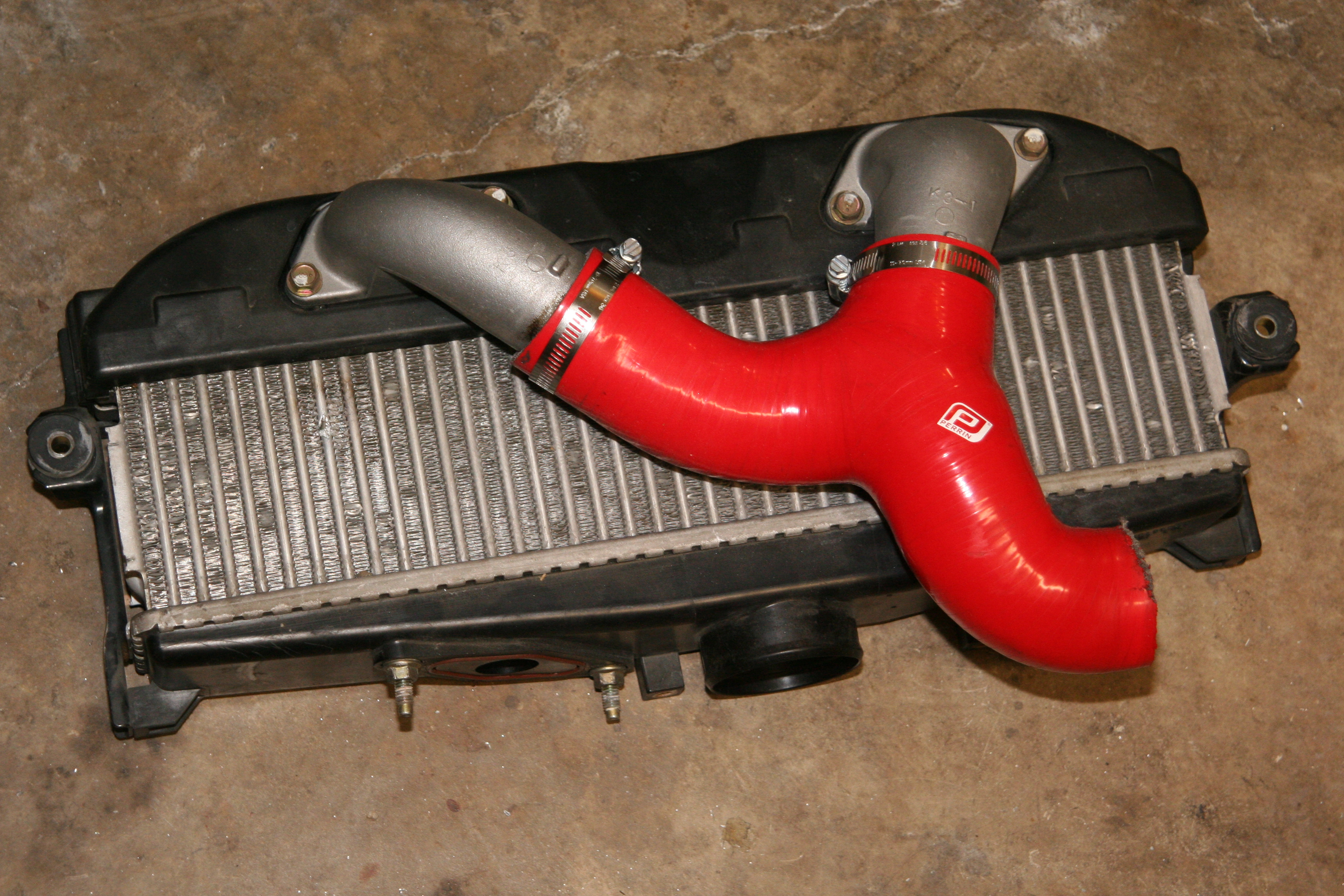
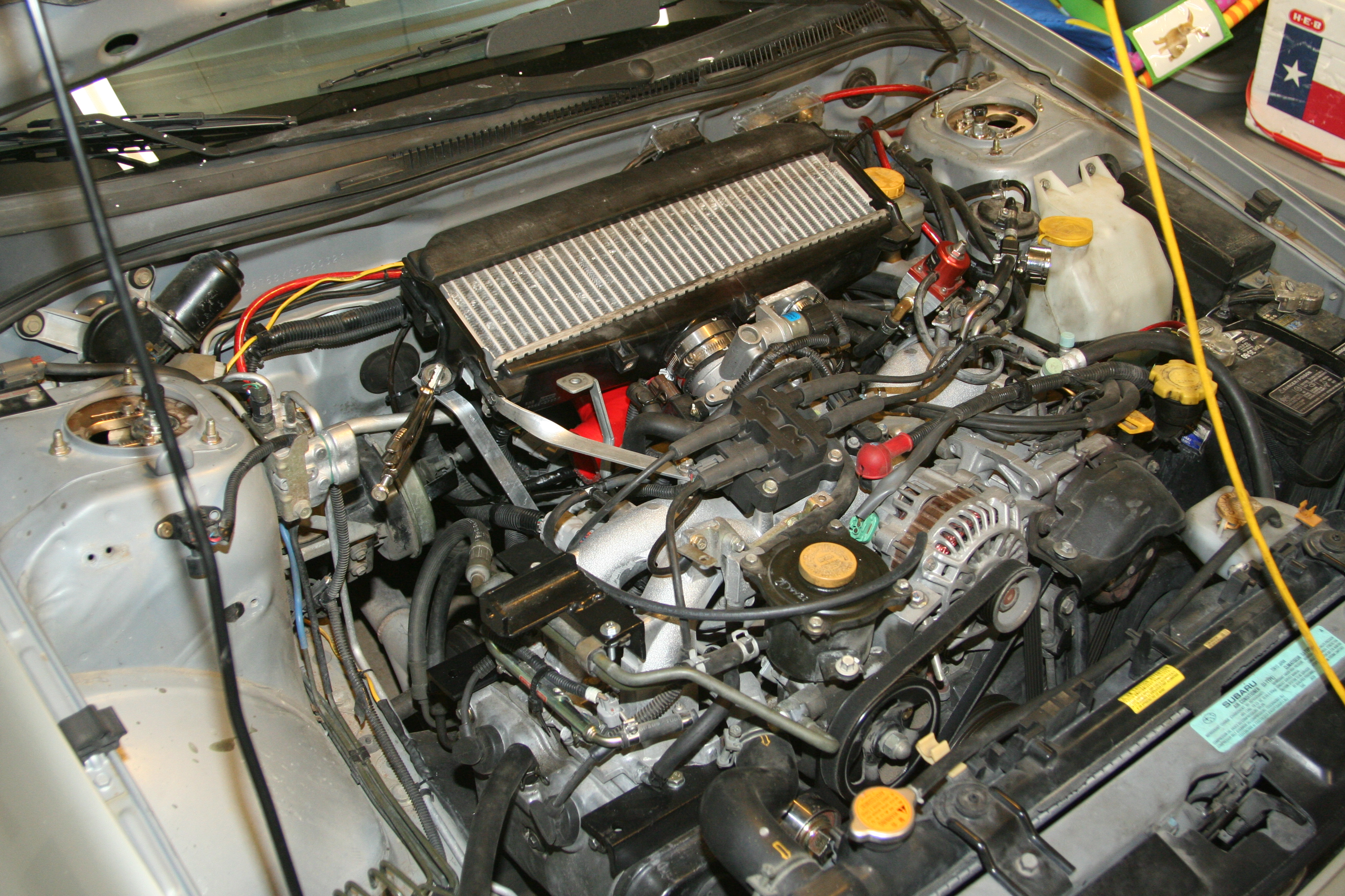
Due to the well known issue of clearance between the Throttle Body and the firewall on the 2000 NA Impreza, I decided to go with something other than a WRX intercooler. The 2004 Forester XT uses a longer, and skinnier designed TMIC over the standard WRX model intercooler. Due to the skinnier profile of this TMIC, there will be plenty of clearance to the firewall. No need to do any triming or anything like that. I know this model of TMIC came on some other Subarus too, but I can't recall which.
The used 2004 Forester XT Top Mounted Intercooler and Perrin Y-Pipe
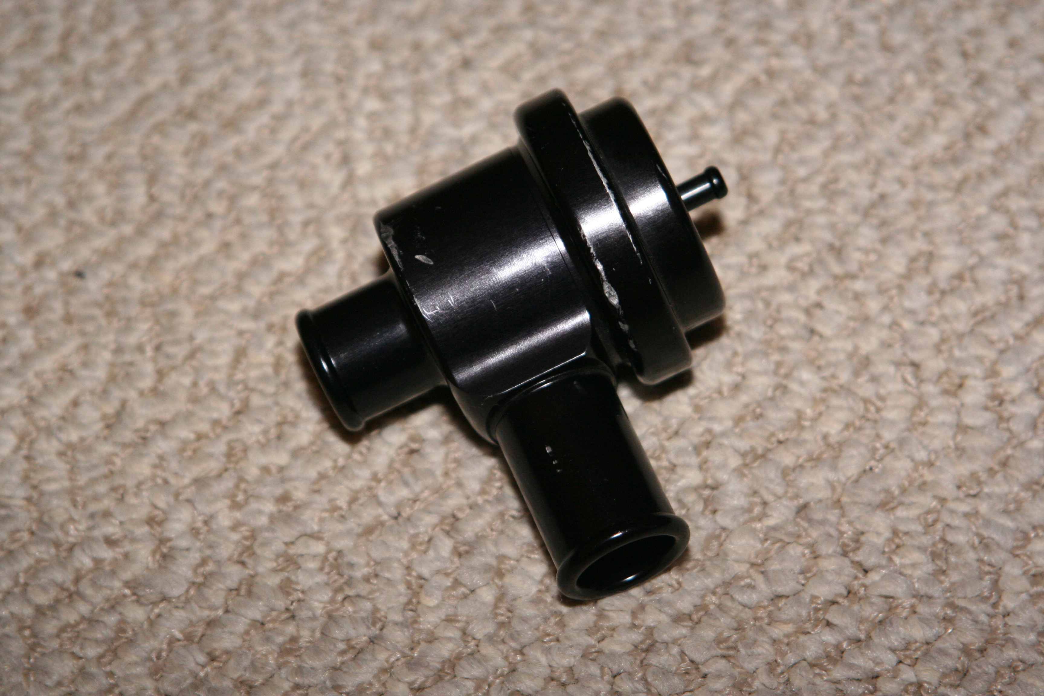
For a CBV (Compressor Bypass Valve) I chose a model by Forge that is basically an aftermarket version of the Bosche BOV used in Porsche and Audi turbo cars. I picked this one up off of EBay for a really good price. It has the lightest spring for this model installed (green). As a result it starts to open at just 2-4Hg of vacuum. At 16Hg of vacuum or higher (idle conditions) it's wide open. I'm going to fabricate a plate and tube to mount to the factory BOV location on the Intercooler. I'm going to run the outlet to the intake on the supercharger and create a fully closed bypass valve system. But, since my car does not have a MAF, but is instead a MAP vehicle, I could vent to atmosphear without any problems. But, since this valve will be open at idle, I'd need a filter on the end of it. So.. I'll just route it back to the supercharger and keep it all simple.
The used Forge BOV/CBV I picked up.
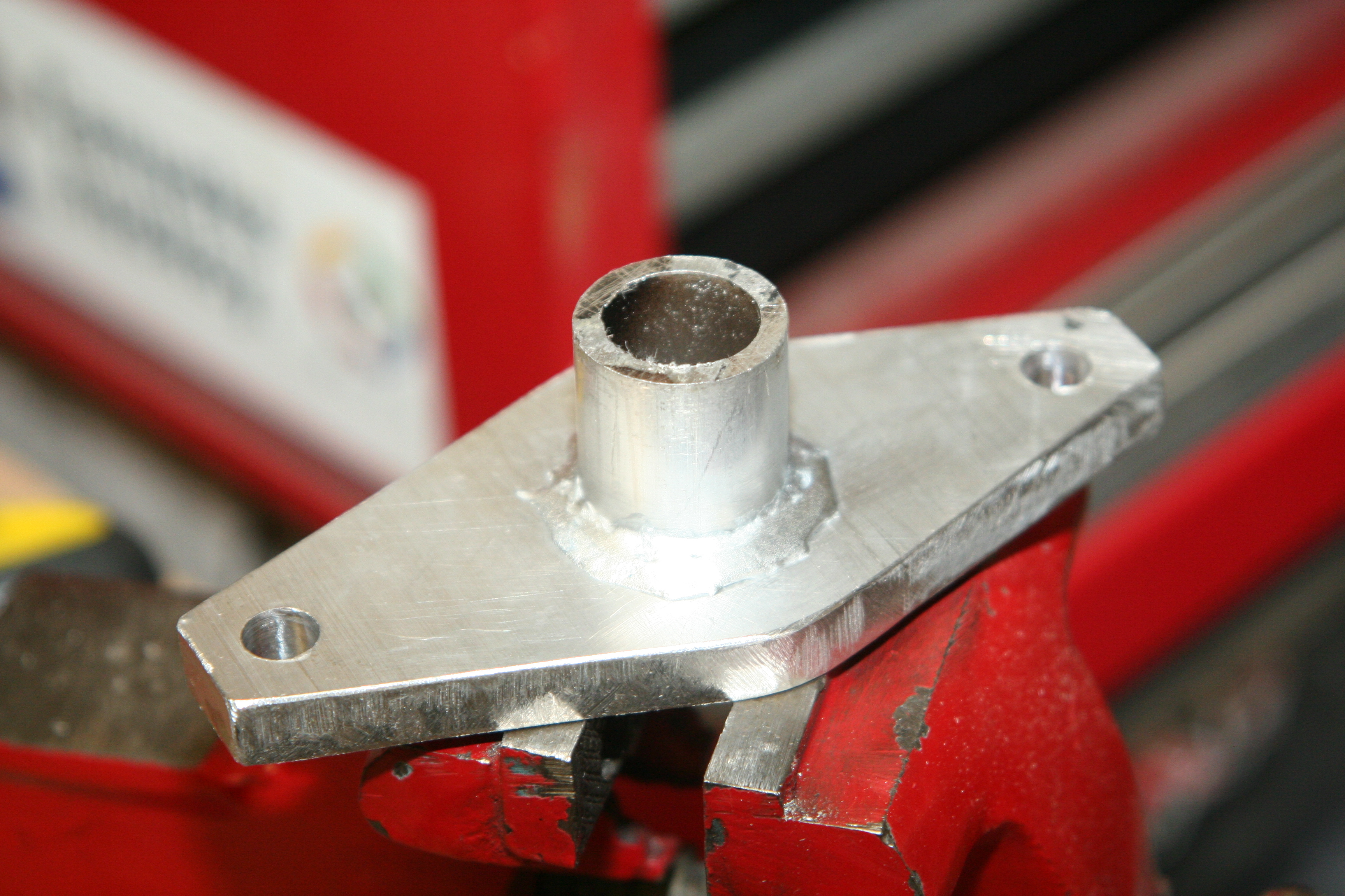
Using a piece of 3/8" thick aluminum, I created a plate to fit where the OEM BOV bolts to. Then using a short piece of 1"OD aluminum tube, I brazed it to the new plate. The end result was a 1"OD adapter to allow me to fit the Forge BOV.
Finished BOV Adapter plate and outlet tube.
The Adapter plate, Silicone Elbow and Forge CBV mounted to the TMIC
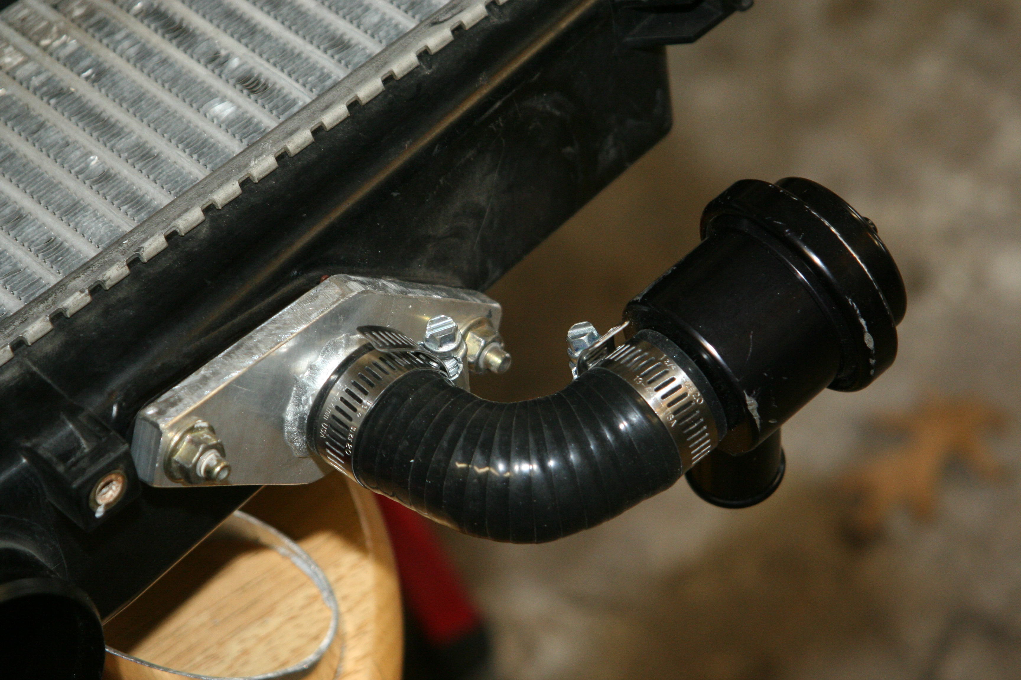
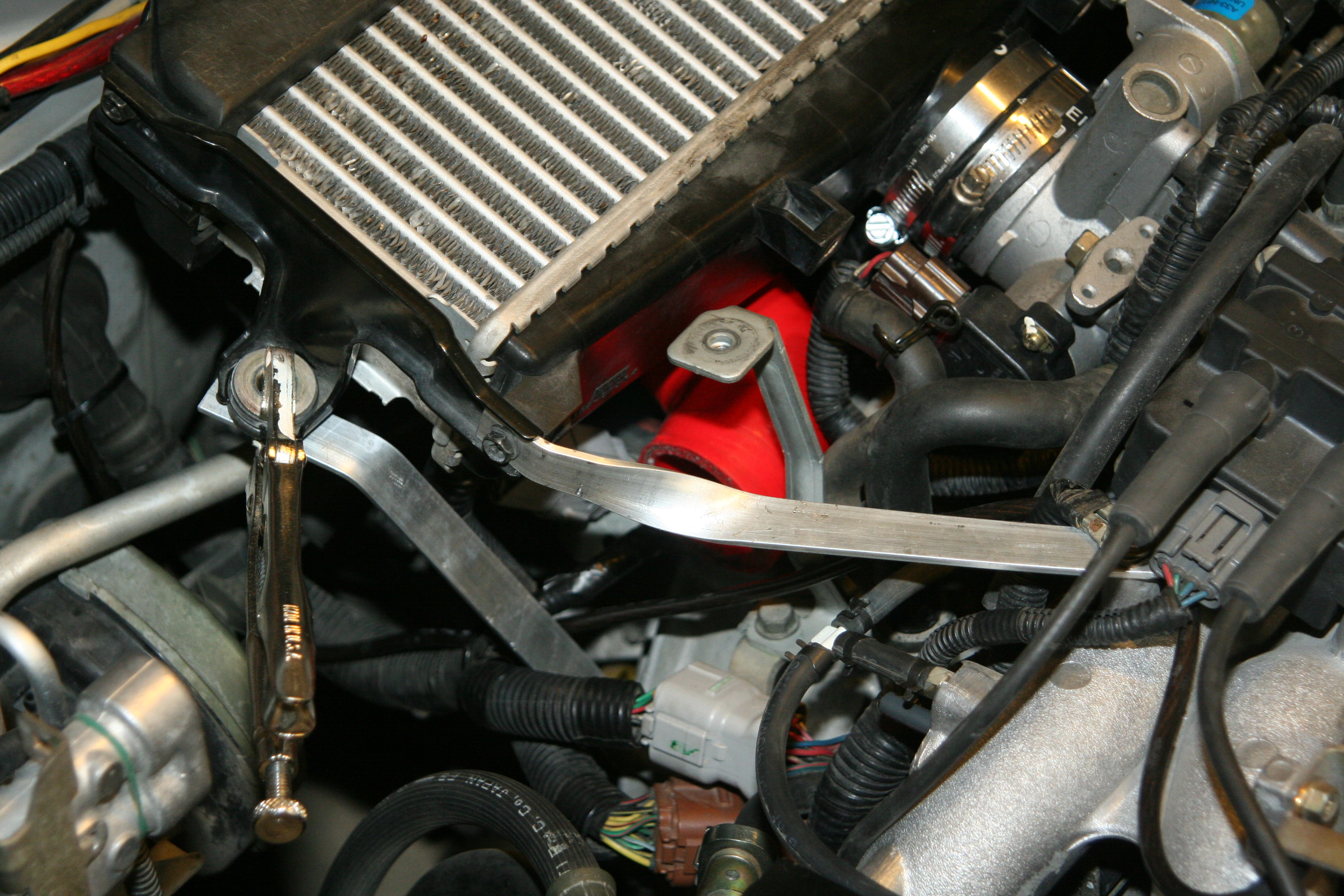
Although the TMIC<->TB silicon coupler is pretty strong, I wanted to incorporate some sort of extra bracing to ensure the IC doesn't shake around. With the IC just held in with the coupler, it was really easy to shake around by hand. So, using some aluminum I create 2 supporting brackets. One that holds the IC still on the vertical plane, and the other on the horizontal plane. As a result, I can not shake the IC at all by hand any more.
The 2 alumimum braces.
Yes, those are vice grips holding the one in place :)
The Supercharger Pressure Side
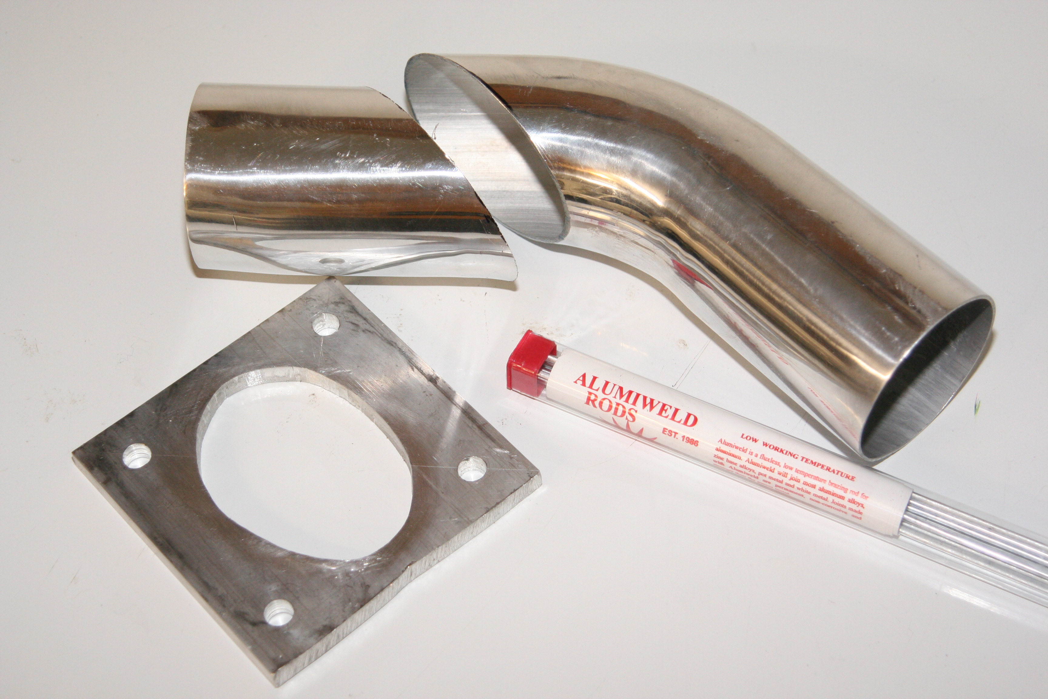
The pressurized air from the Supercharger has to take a bit of turn out the side back towards the intake manifold now. I'll start with a 5"x5" piece of 3/8" thick aluminum plate (from speedymetals.com). I measured out, and drilled 4 holes to match the 4 mounting holes on the supercharger. I then took a 3"OD 45o 2mm thick elbow and cut it at 45o. The result was a 90o turn with a larger opening at the supercharger end. After tracing the outline of the 3" tube onto the aluminum plate, I cut out the elliptical opening in the plate. Now, using some [aluminum brazing rods I got at Harbor Freight],(http://www.harborfreight.com/cpi/ctaf/displayitem.taf?Itemnumber=44810 ) yes.. that's right brazing rods, the elbow is welded.. uh.. brazed to the plate.
Note: about the aluminum brazing rods. Spudchucker (on rs25.com) is also doing a way radical custom M90 install on his Impreza. He is going about it quite different than I did, but he is also using these brazing rods. He found a little trick that proved very helpful to him. He was having trouble getting enough heat into his very thick pieces of aluminum to get the rod to melt nice. He ended up eating up o2 bottles way too fast. So, he got smart. He fired up his BBQ to pre-heat the parts. His BBQ was more than enough to get the thick aluminum up to temp (750F). In fact, I believe he didn't even need his torch to finish the brazing. So, keep that in mind if you give this a try.
The 3"OD 45o elbow cut at 45o. and the 3/8" thick 5"x5" mounting plate with the oval hole cut to match the tube. And, the alumiweld aluminum brazing rods.
The cut 45o elbow sitting in place on the 5"x5" plate before being welded
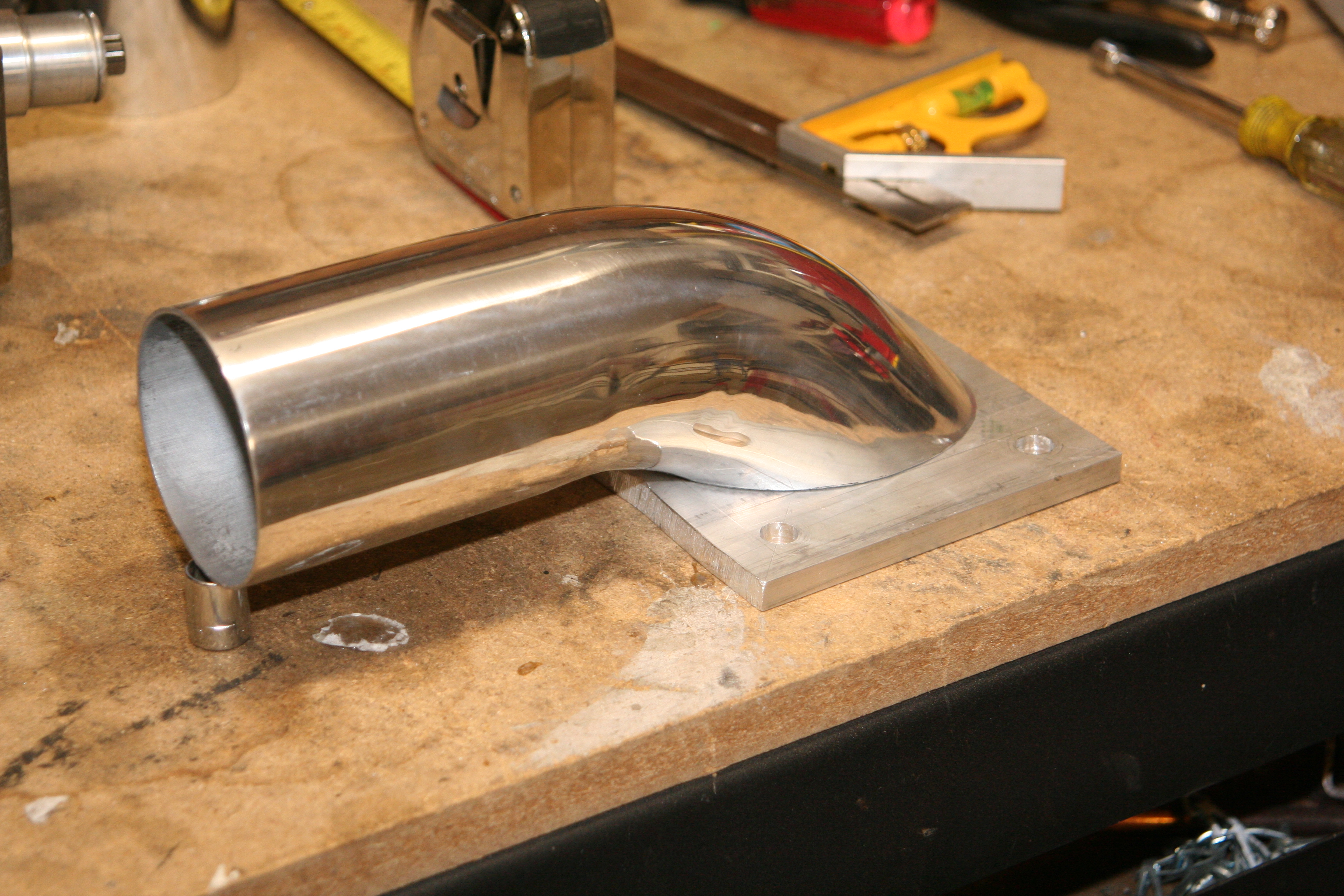
A closeup of the aluminium brazing results. Look pretty good if you ask me!!
The underside of the exhaust plate and tube. I used my Dremmel and a few sanding tubes to smoothen and finish the plate.
The pressure side with a Silicone 45o 3"->2" reducer elbow mounted to the Supercharger.
The Supercharger Intake Side
NOTE: I'm in the process of changing the intake side... see Part 7 for details
Now, to feed filtered air into the Supercharger. The intake side was not too difficult to fabricate. Just had to get a little creative. I started with a 2"x3" piece of thin wall aluminum box tubing. Cut to ?" in length, I brazed a pair of rectangular plates to each end, creating a sealed box. It was then a simple matter of transferring and cutting the outline of the superchargers inlet opening to the side of the box, as well as the bolt hole locations. On the other side, I created 4 much larger holes that line up with the main bolt holes. These hols will be used to allow 4 large allen-wrench cap-head bolts to be inserted. Once I was done with all the high-heat brazing, I used 4 plastic bolt-head caps that I got from Lowes. These plastic caps can be snapped shut, or open with a screwdriver. I used a bit of JB-Weld to secure these caps over the larger holes. Since the intake side sees only vacuum, these caps should hold just fine, and keep any dirt out easily.
Photo Pending
I then used a length of 3" OD tubing with one end squished to fit on the 2" side of the box. I traced the outline onto the box, and cut out the oval opening. Then, once again brazed the tube to the side of the box. This tube is where the flexible Spectre intake hose will secure to feed filtered air from the fender well. A thin coat of RTV applied to the mating surface, 4 cap-head bolts, and the intake plenum is secured.
Intake and Exhaust all mounted up
Air Intake and Filter
The intake side is going to be both easier, and trickier at the same time. It'll be easy because it will not need to hold any pressure. But, tricky because I want to route the air filter to the fender to get cooler air in. Time to be a little creative now.
I started with a piece of 3"x2"x1/8" aluminum box tube to create a sort of intake plenum. I chose 3"x2" because the inside area of the box is equal to the area of the supercharger opening. The supercharger inlet is 3.75"x1.3" for a total area of 4.8"2. The inside of the 3"x2" box is 2.75"x1.75" for a total area of 4.8"2. This way there is no major change in restriction for the air coming in.
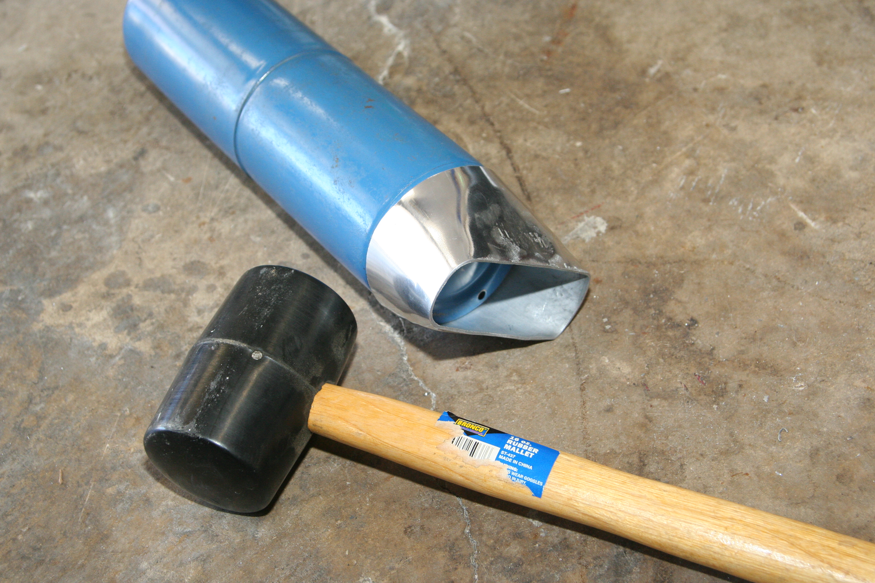
Next, I flattened one end of a piece of 3"OD tubing to fit inside the 2" width of the box tube. Note, the approximate area of a 3" tube is close to 7"2, so it is also not a restriction on the intake at all. The photos show a different piece of 3" tube I flattened.
More info coming
The propane cylinder on the end of the 3" tube.
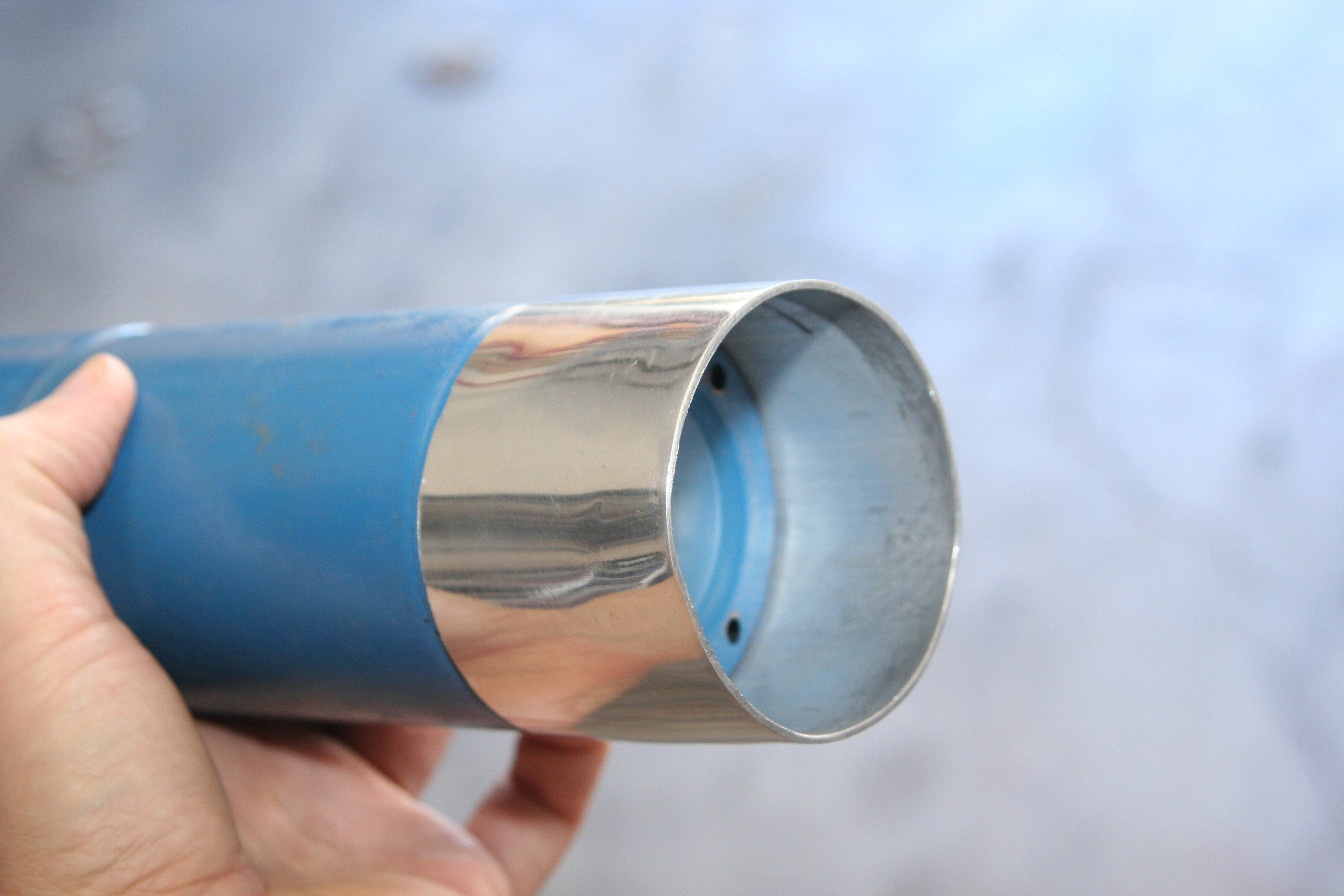
A hand full of whacks with a rubber mallet.
Air Filter
Since I will be putting the air filter right inside the fender, I chose a filter with enough surface area to feed the CFM demands of my motor, but one that was still small enough to actually fit inside the fender. I decided to go with teh K&N RB-0900 universal filter.
K&N RB-0900 Air Filter
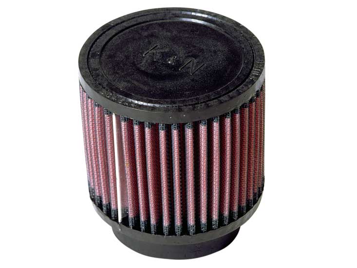
Why this filter? The Stock Panel Air Filter in my FXT is 11"x6.5" around the outside. Take into account the rubber edge of the filter, and it's more like 10"x5.5" of filter area. This tallies up to 552" of actual filter area. So, if the Turbo Charged FXT is happy with that amount filter area, then as long as I can find a filter with at least that much area, I should be fine. Sure, more is always better, but in this case I'm keeping within factory specs.
Also, I found a random [air filter area estimator](http://www.banzairunnerpantera.com/techinfo_calcs.htm . After plugging in the values for my NA 2.5L, it calculated a filter area of 392". Since I'll be super charged, I'm going to pretend my engine is bigger than 2.5L for this estimator. Plugging in 3.5L of displacement at 6500 RPM comes up with 57.52" of filter area.
Looking at the specs on the K&N RB-0900 page, I can calculate the surface area of the filter. It comes almost spot on the same area as the stock FXT filter. * 4" high at the filter section. * 4.5" Outside Diameter (equal to 14.1" circumference) * 14.1 * 4 = 56.42" of filter area.
I had to open up the hole in my fender well just a bit to get this filter in. Not much cutting was needed, but it's clear in the photos on the following pages what was removed. This filter coupled with one of those 3" flexible air intake ducts made by Spectre (from PepBoys) provided the flexibility I needed.