Build Part 7
Relocating the Throttle Body
The Throttle Body Move is a success. And not just a success, but a big success! The supercharger is a whole lot quieter, but still very audible. Throttle controlled power delivery is way easier to manage. It wasn't a trivial thing to accomplish, but trust me, it's worth it. See the [[2000_Subaru_Impreza_2.5RSC_Build_Part_6|previous page]] for an explanation.
Words can only go so far, so this page as a great deal more photos than previous ones. But, see all the photos I took during this TB relocate
Parts and Materials
- Used Throttle Body
- short piece of 2.5"OD cast aluminum tube.
- 15" length of 4"x1/4" plate aluminum
- 12" length of 2"x3"x1/8" box aluminum tube
- 1"OD 90o Brass Elbow (plumbers section at Lowes)
- 1"OD-5/8"OD Brass T-Adapter
- 5/8"OD Brass Coupler
- 5/8"OD Nylon/Plastic 90o Elbows and T-Adapters
- 5/8" ID rubber hose.
- 3"OD Spectre 90degElbow
- Silicon 90deg 3"OD -> 2.75"OD Elbow
- JB-Weld & more of that Alumiweld Aluminum Brazing Rods
Modified TB and IAC
I knew that where I planned to place my TB was a tight fit. I didn't know exactly how tight, but I knew enough to see that the stock TB was too big. At a minimum, the Idle Air Control Solenoid had to go. I don't know if I needed to, but I also shortened the linkage to ensure it cleared the side of the SC.
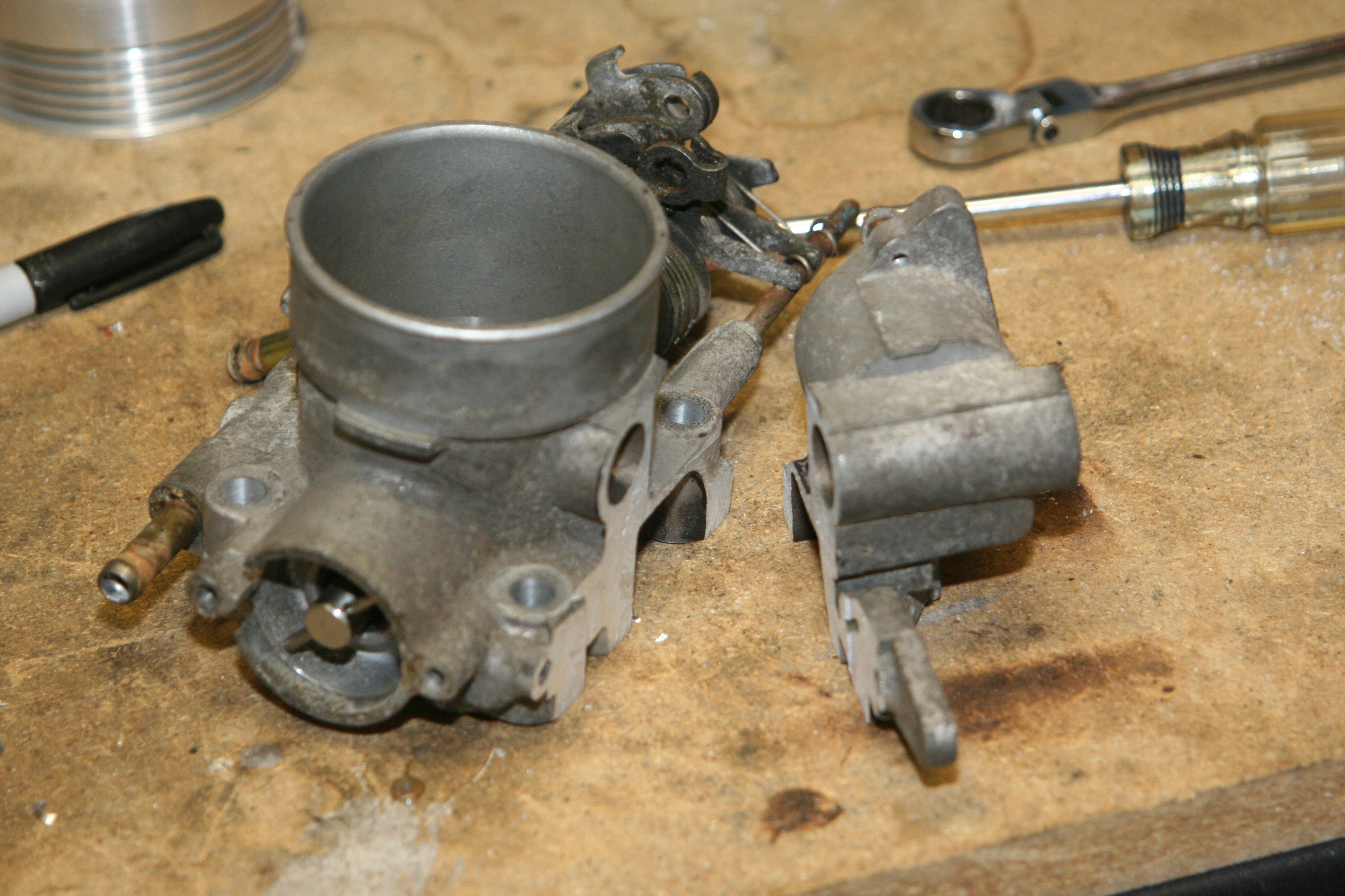
Next, I took my newly acquired TB from a 99 EJ25 (could have also used a 00-01, but I liked not having the AirAssist port) and cut off the IACS part, and the TB Heating Ports from the other side. The Heating Ports are the 2 brass and rust colored tubes to the left of the TB in the photo below.
I also used a piece of tape on the inside of the TB, and a bit of JB weld to seal up that hole created by removing the IAC housing. You can see the sealed hole a few photos down. The tape is to ensure the JBWeld hardened nice an flat to the inside TB surface.
TB with IAC housing hack-sawed off
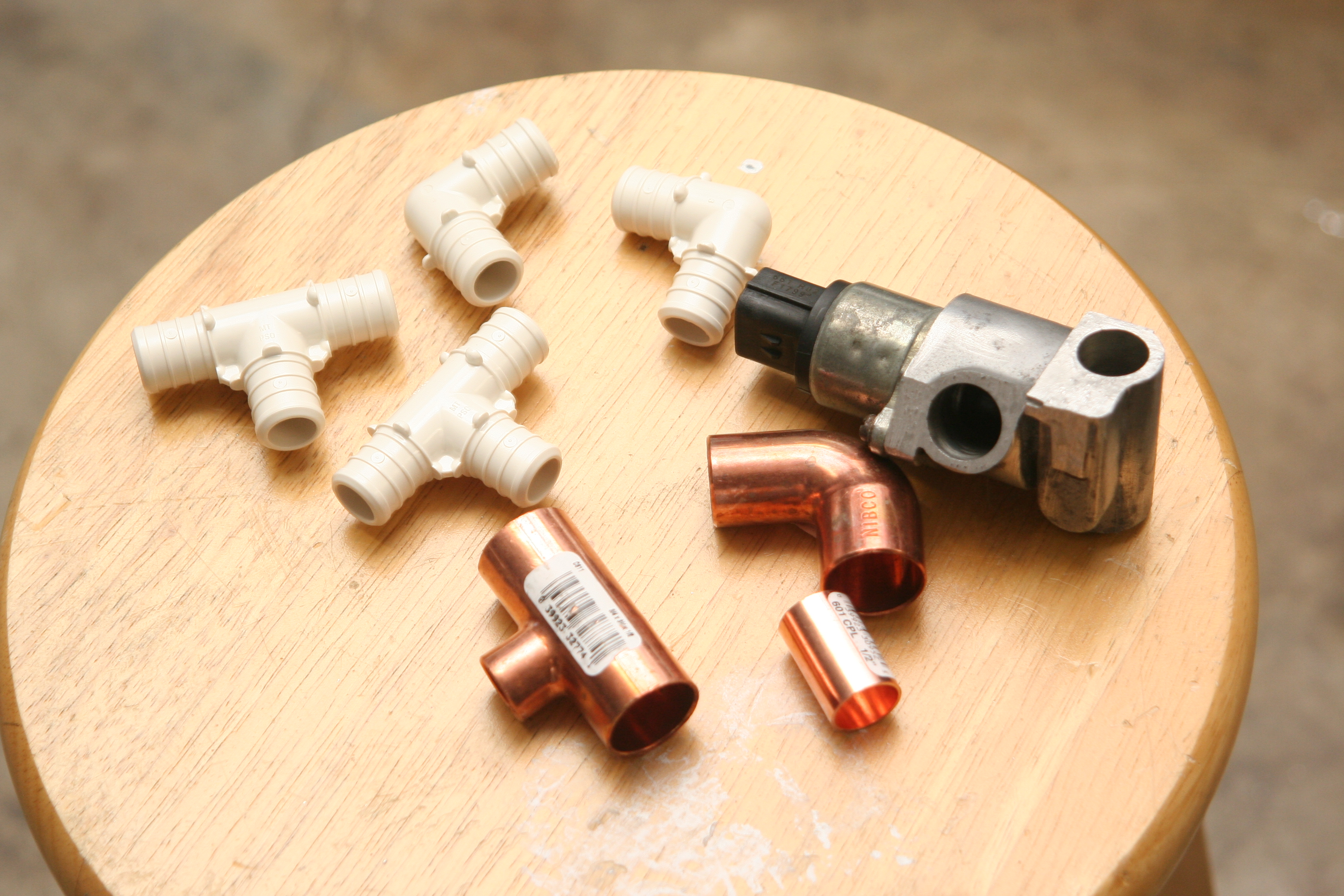
Next, I trimmed off the un-necessary bits from the now removed IAC housing.
|The final result of the cutoff IAC housing, with the IAC bolted in
Plus, the extra tube and pipe bits I'll be adding.
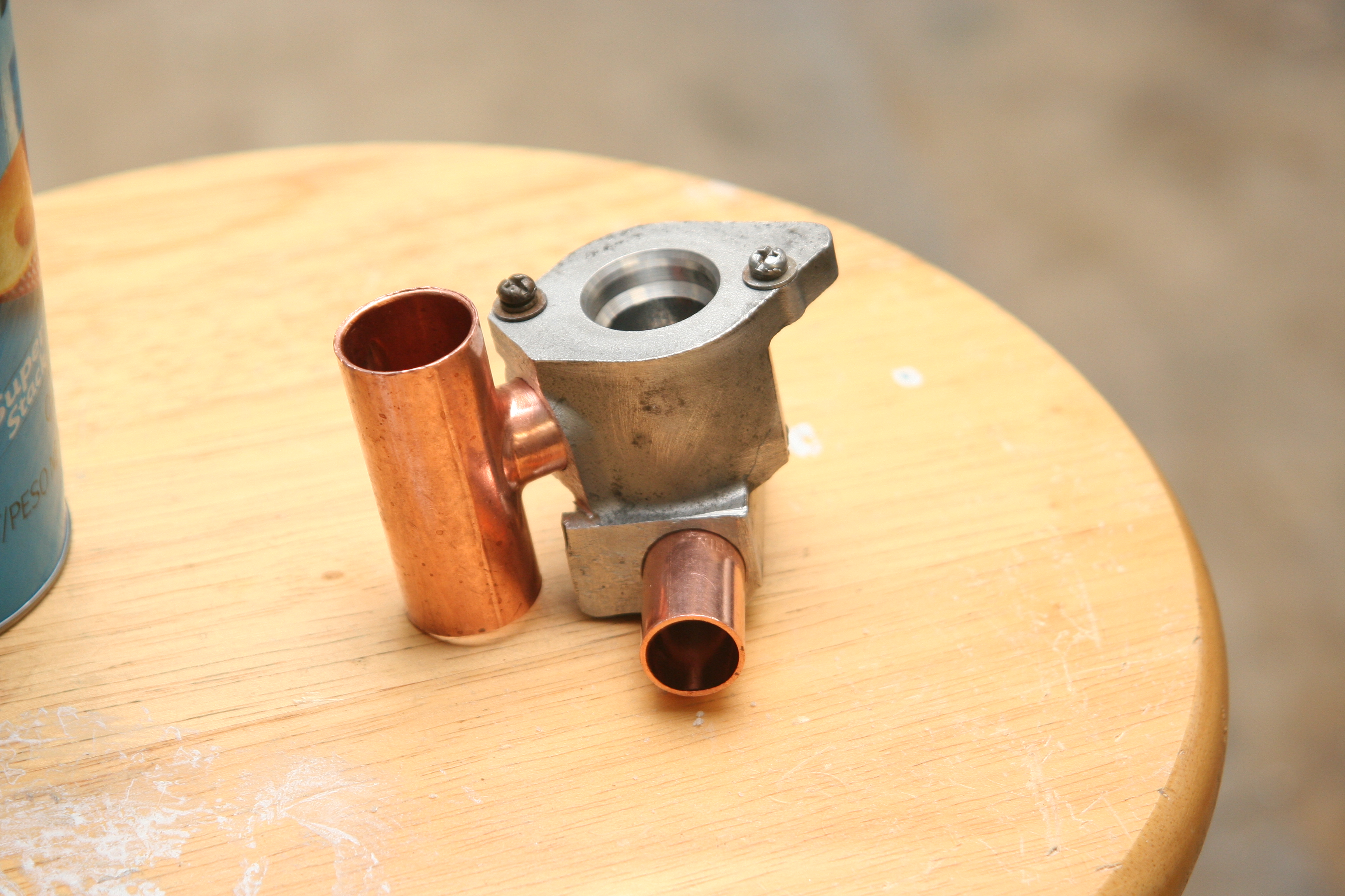
Here you can see the plumbing pieces inserted into the IAC housing. I jammed them in as tight as I could, then used JB Weld to make them permanent. Note, the T piece is not necessary if you don't intend to use a CBV. I currently don't have a CBV installed, but one day plan to. So, the T is used.
IAC housing with copper plumbing bits inserted. JBWeld to follow.
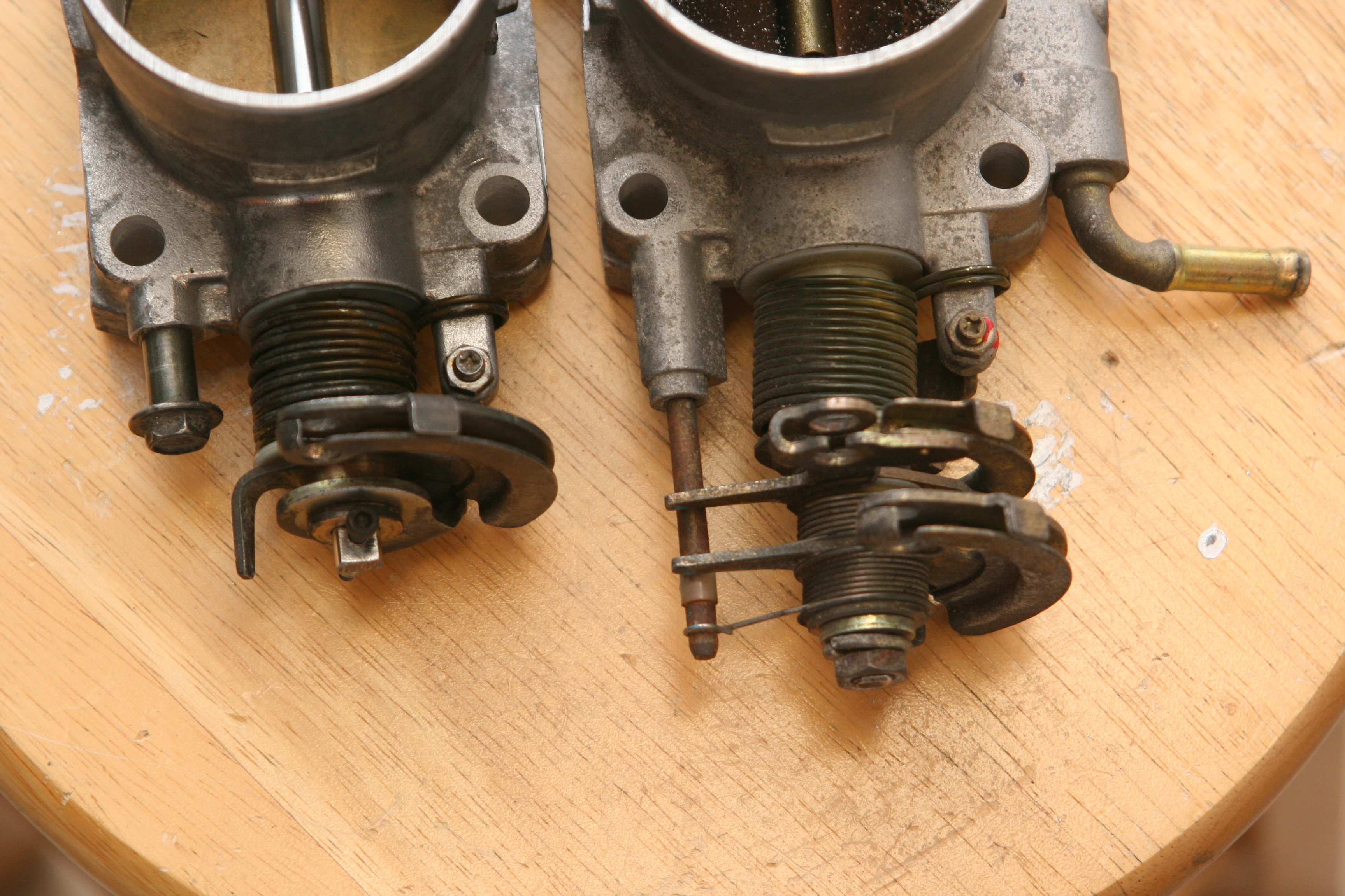
Now, I need to shorten the Linkage. As I stated above, I'm not totally convinced any more that I needed to do this. In fact, since I have a 3rd TB on hand, I might try again with the linkage left intact. But, until then, this is how it's currently configured. It's really pretty simple to do, but too detailed to explain here. Hopefully you can make sense of what I did by referencing the photos below. The goal was simply to shorten the length as much as possible. I had to sacrifice my Cruise Control, but my daily commute is 4 miles. I don't miss it, yet!
Note, I cut off the aluminum stub that also acts as a throttle stop. I should not have done that. That is the reason for the bolt inserted into the side of the TB. I should have only cut off the metal rod part. Oops!
|Original on Left, modified on Right.
You can see the throttle stop bolt I had to add.
Plus, the JBWeld plug where the IACV used to be.
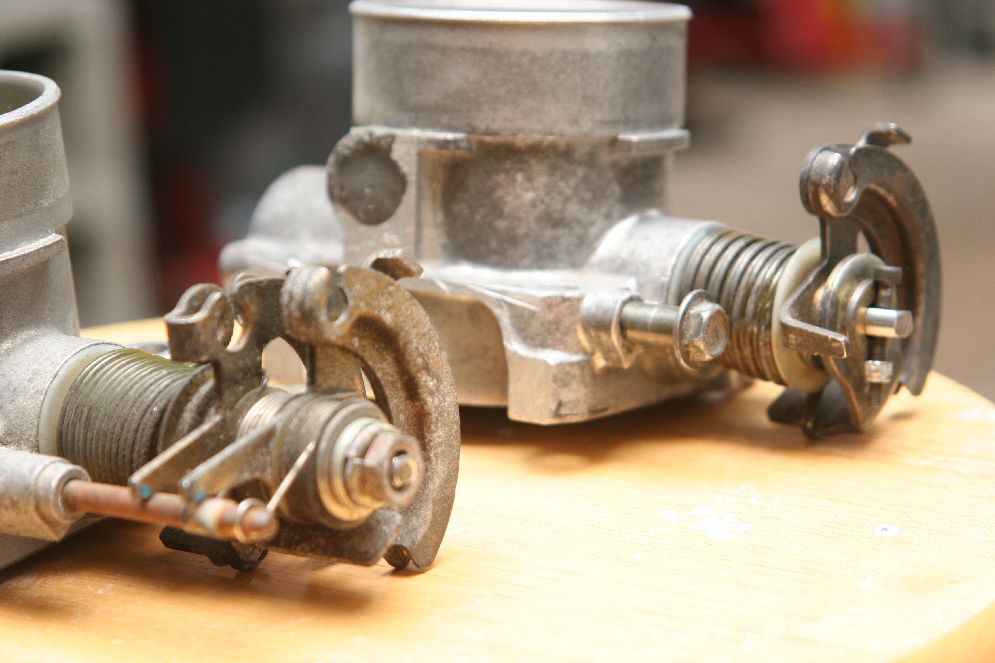
You can see that I shortened it by almost 1/2
The Final result of modifying the TB and IAC
Except that the IAC bit isn't showing the Copper tube JB-Welded in.
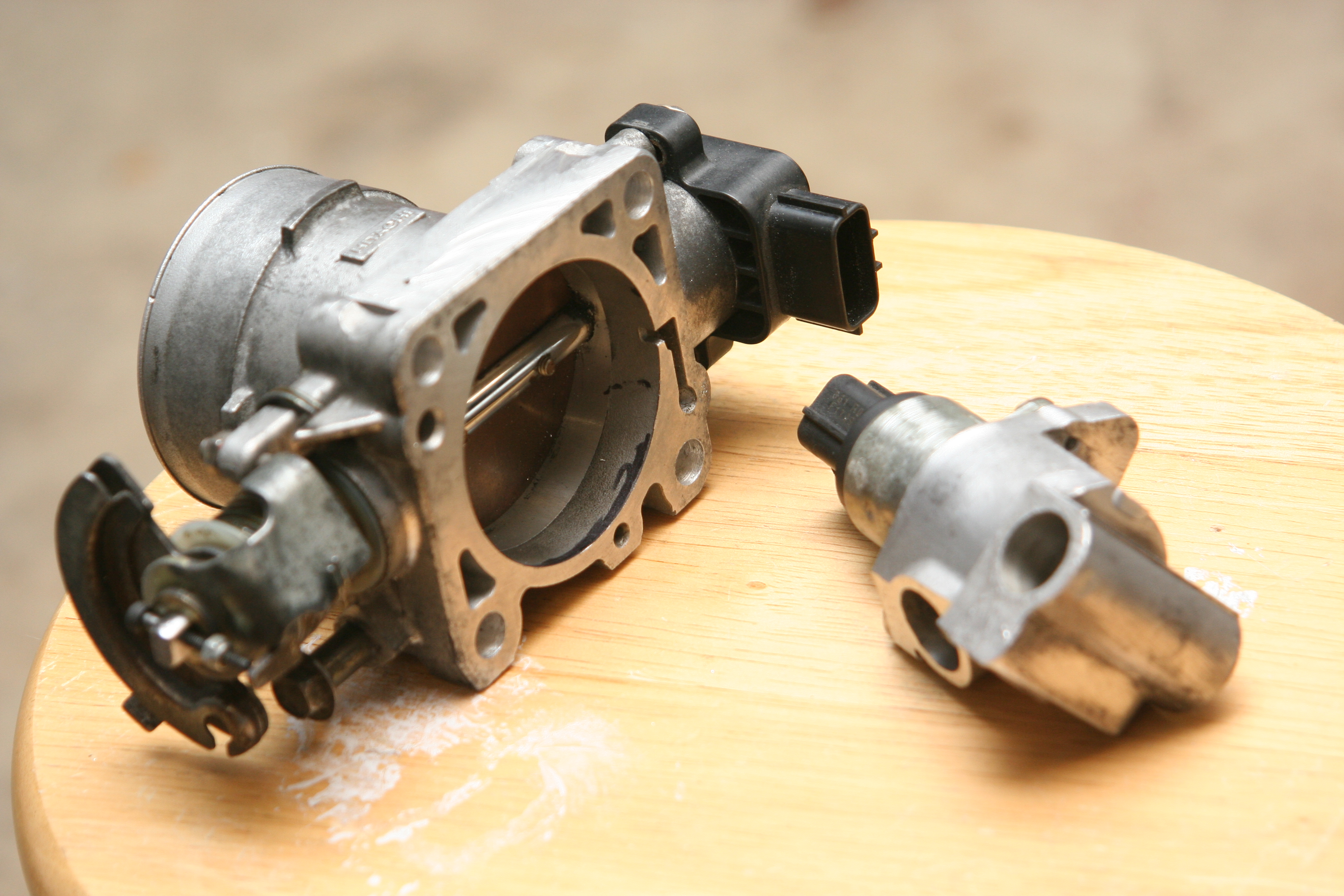
Notice in the above photos that I also reversed the TPS sensor. Since it's symmetrical, it works perfectly fine if you rotate it 180 degrees around. I did however plug the small drain hole, and create a new one opposite of it. This is because, as you'll see, I mounted this TB upside-down from normal.
All Throttle Body Move Photos
Redesigned SC Intake Plenum
Now for the fun part, designing and building an intake plenum of sorts to put my TB out front! I knew I didn't want to have to move my SC, so I had to work with the space I had. Alas, there is indeed enough room. It's snug, but it fits!
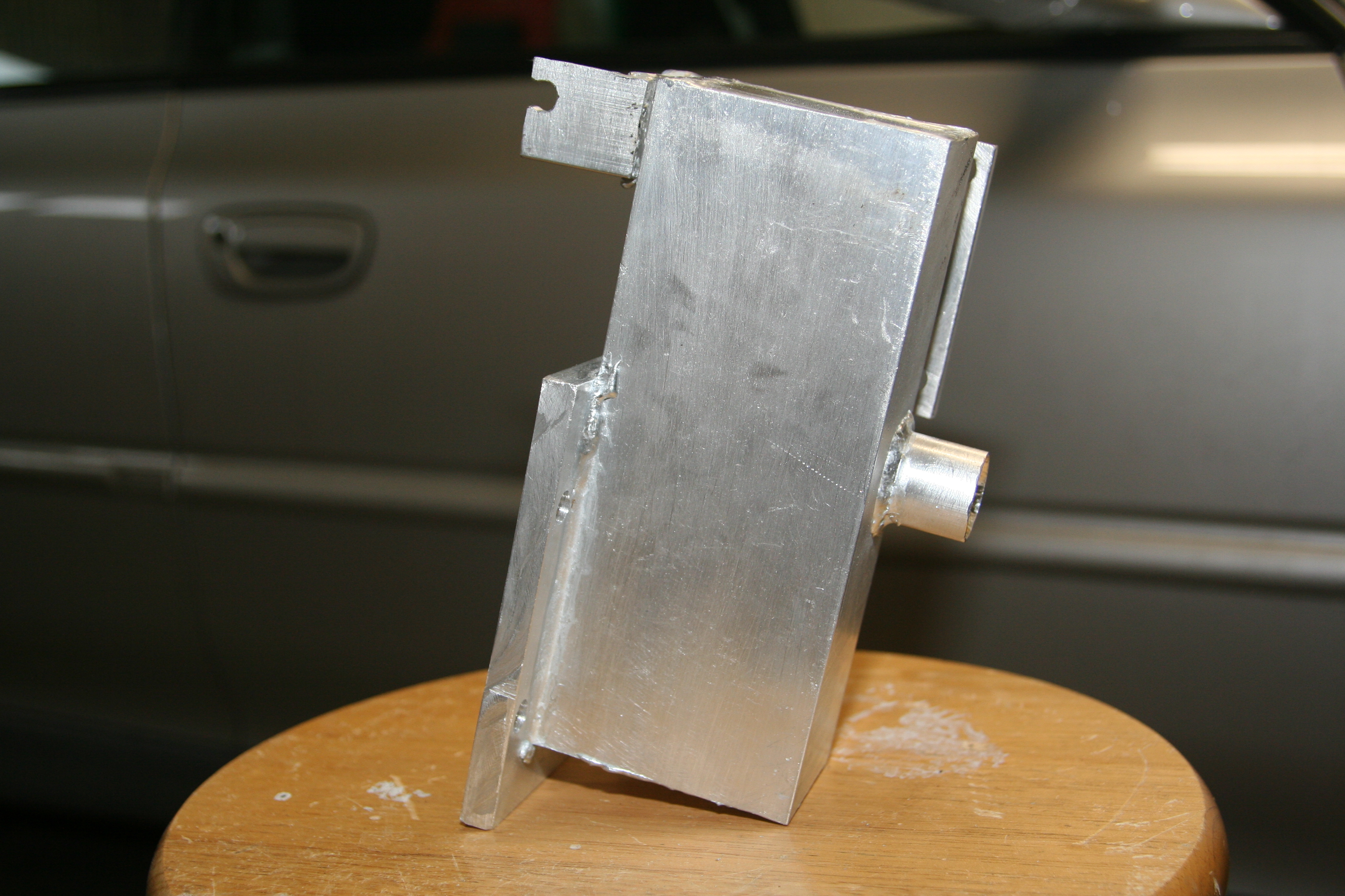
I'm not going to walk you though how I made this piece. I think detailed photos and a diagram speak a thousand words. So, here are a number photos from various angles with descriptions.
The TB mounting flange
The short tube on the left is where the IAC will feed idle air.
It's also where the CBV (if I install one) will return.
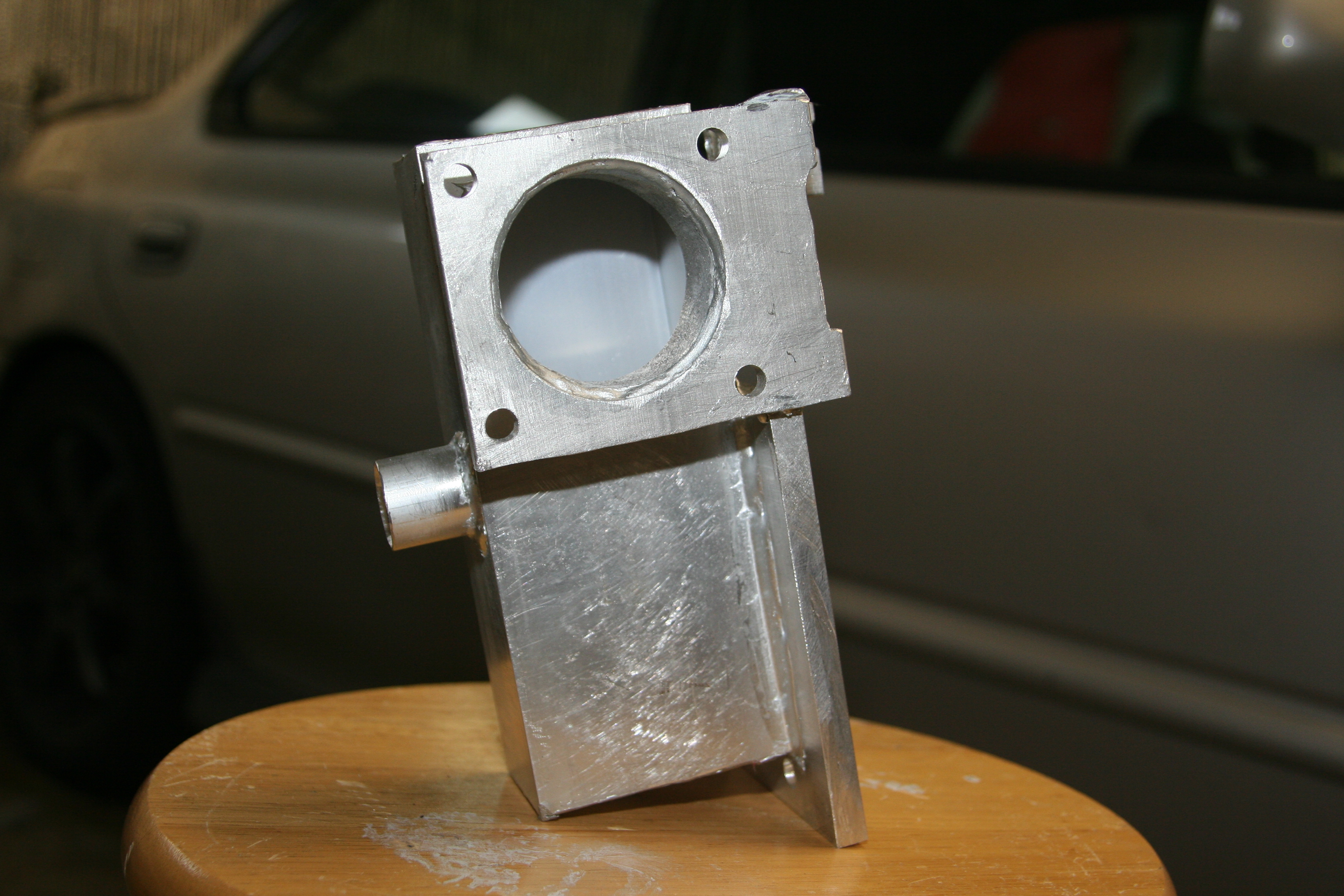
Side view of IAC inlet tube.
This tube is also directly above one of the SC mounting bolt holes.
3 of the 4 bolt holes are external, but this one requires this hole for access.
|-
|[http://www.ludicrous-speed.com/g2/main.php/v/OurRides/ShanesRide/mods/25RSC/MovingTheThrottleBody/1_00007.jpg.html
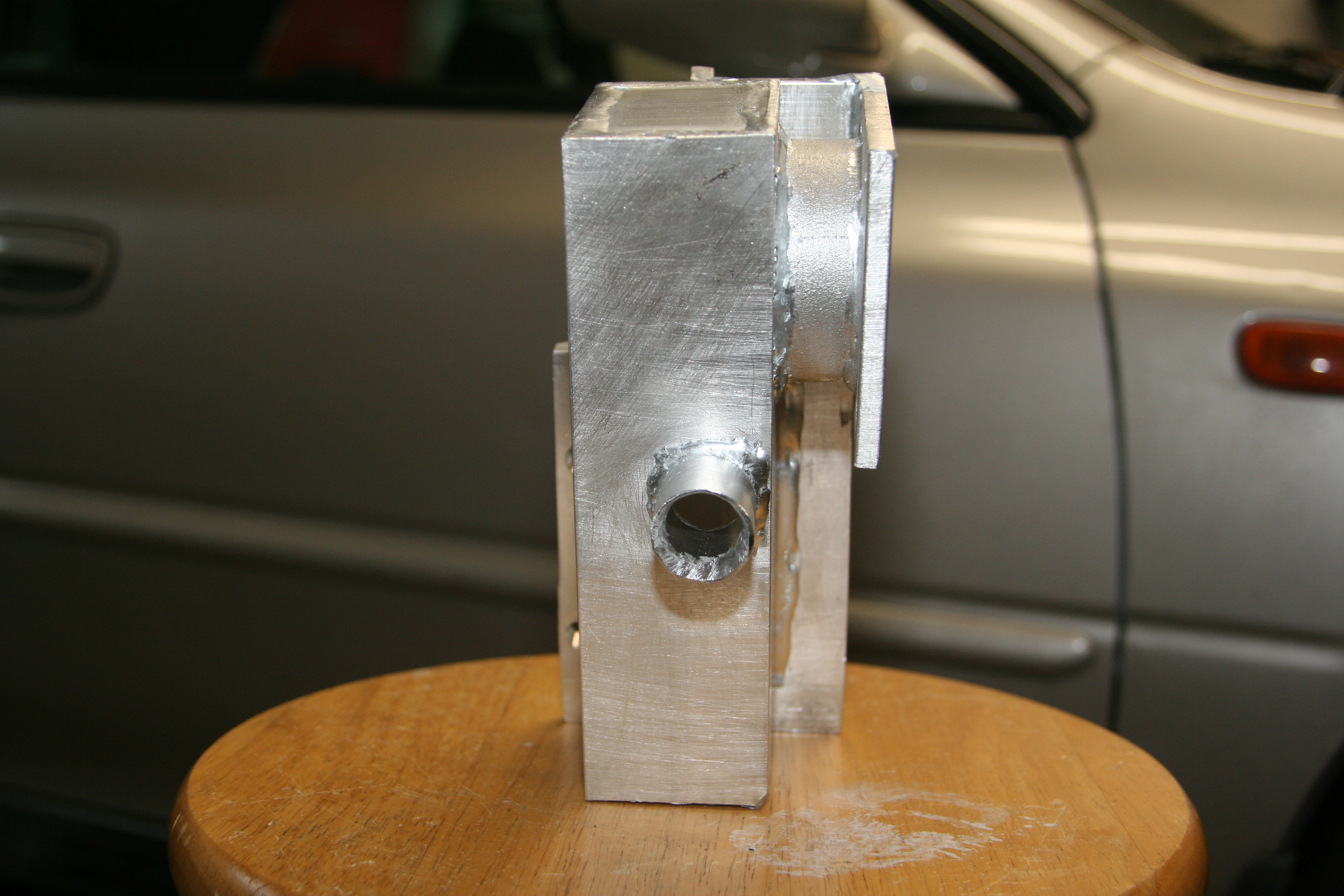
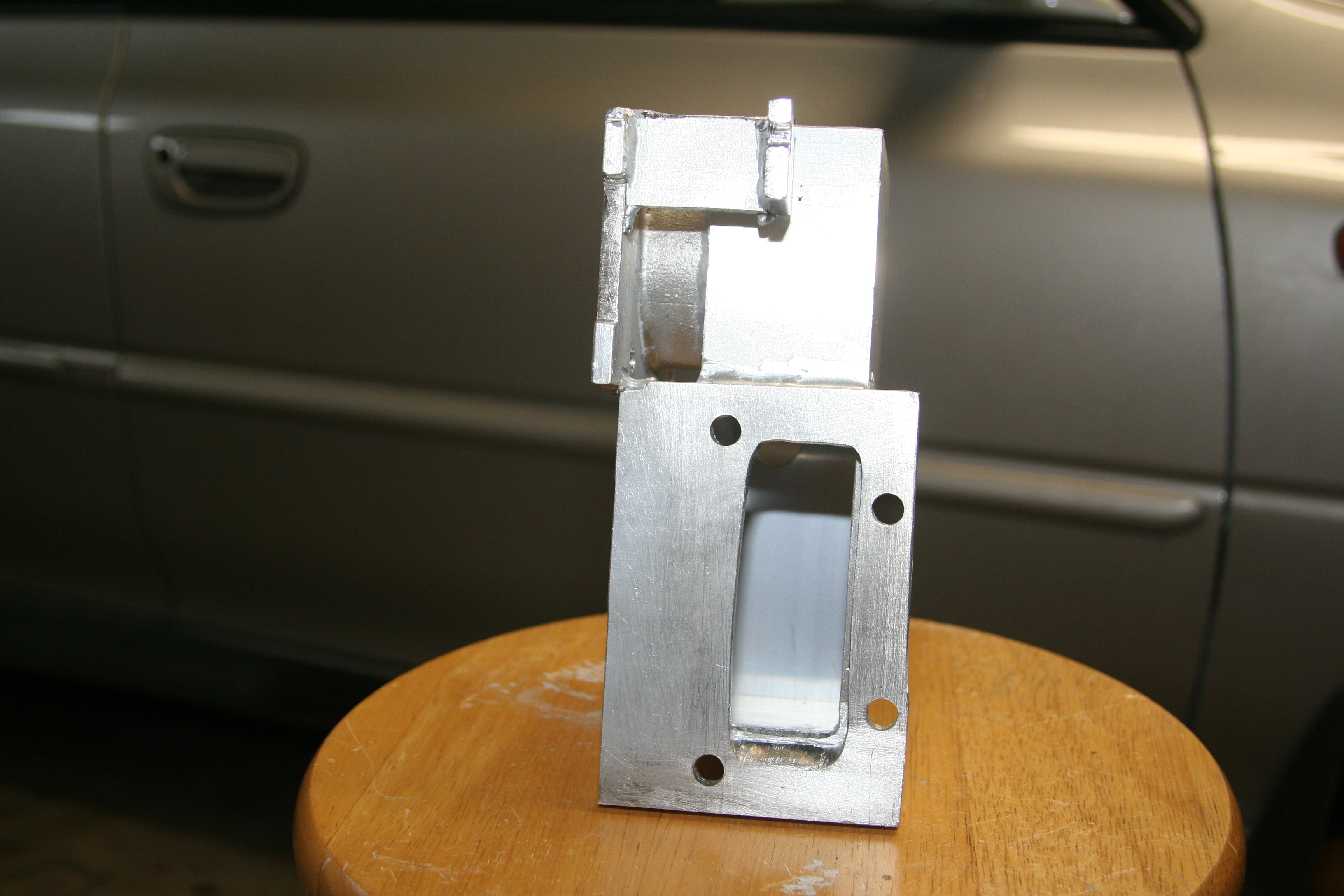
Back Side
You can see the Throttle Cable mounting tab at the upper left.
The SC mounting side
Notice again the Throttle Cable mounting tab. The cable was long enough
that I could have welded the tab to the side of the main box.
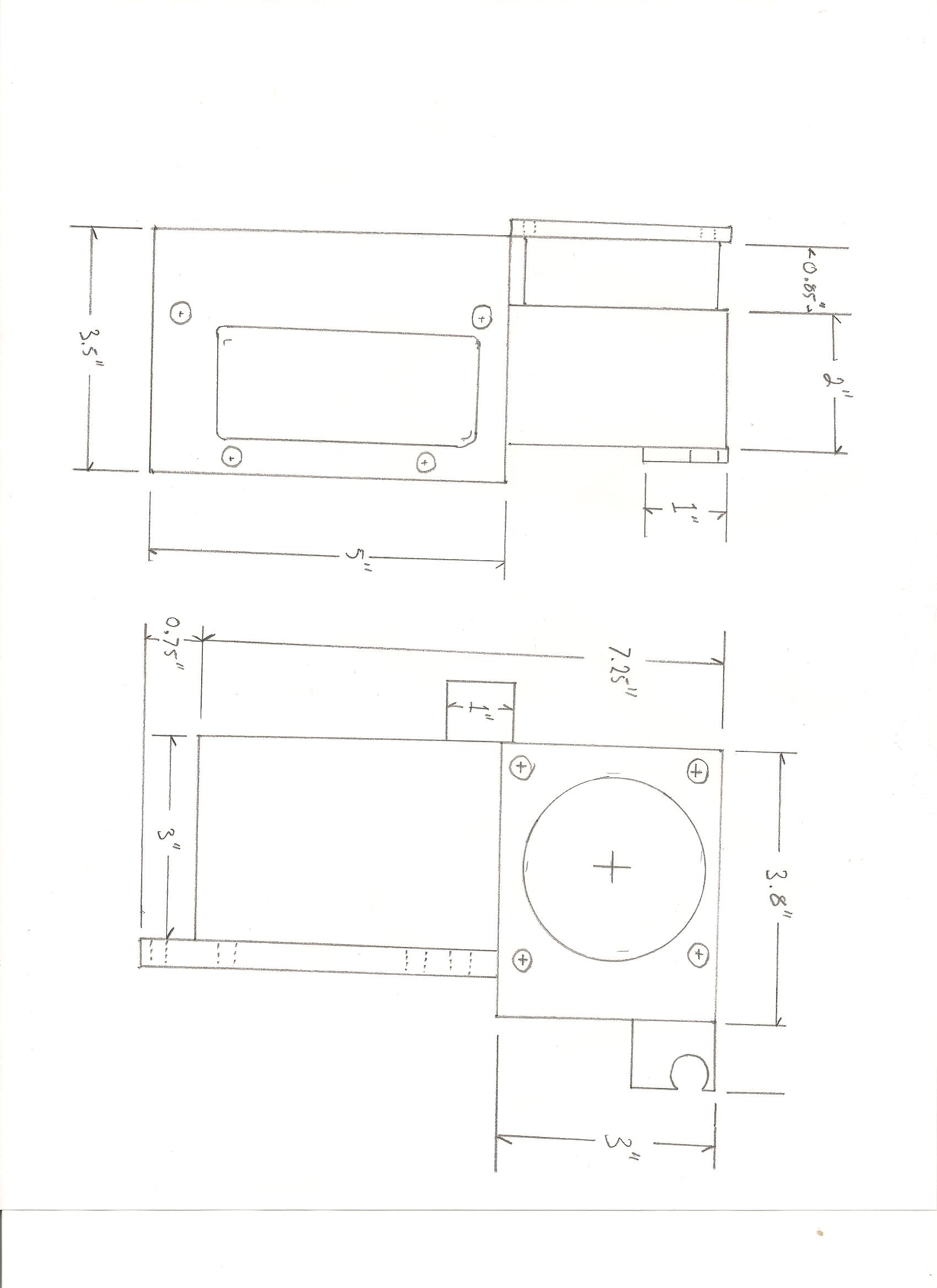
See the measurements diagram for a better idea of how.
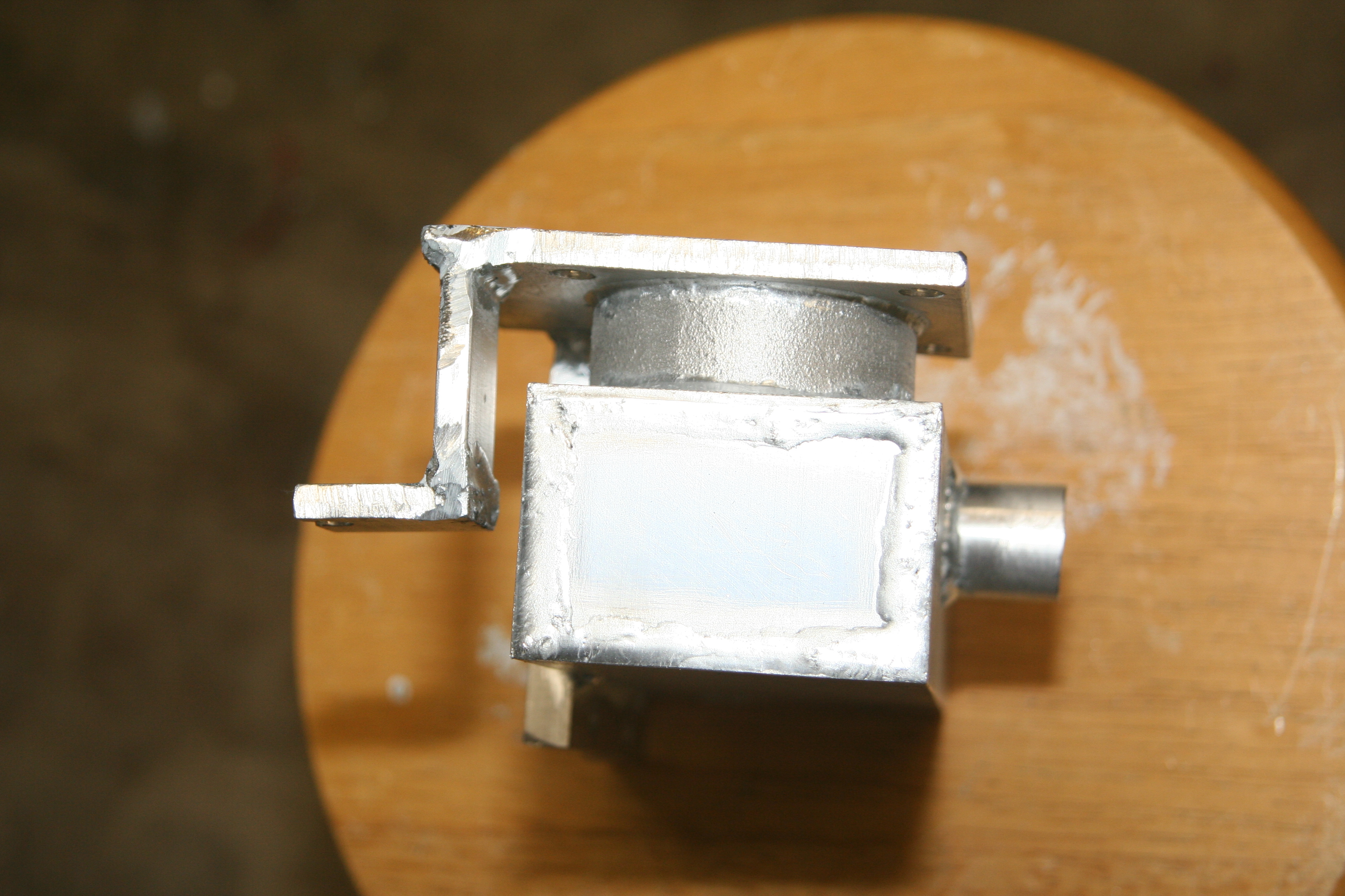
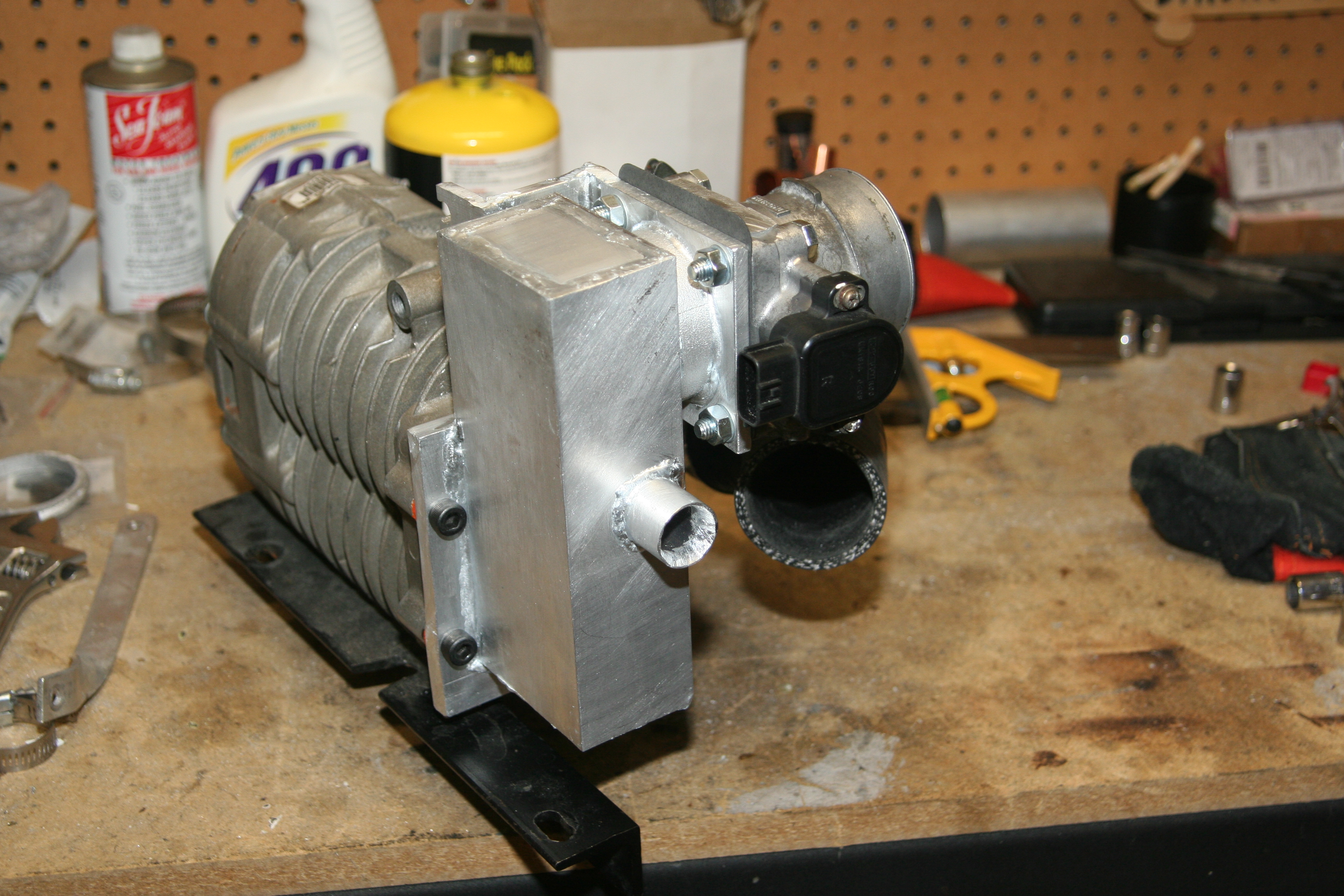
From the top
Once again, the throttle mounting tab on the left.
And you can clearly see the short cast aluminum tube at the TB flange.
An angled view of the business side
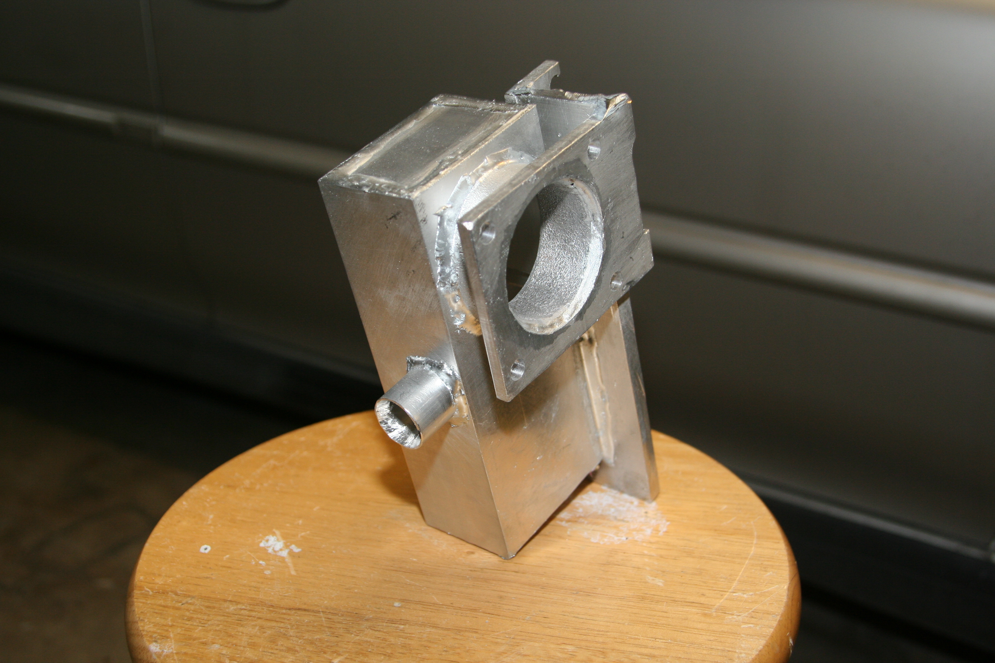
I used a piece of cast aluminum tube to secure the TB flange mostly because it's what I had on hand. I suspect a regular piece of aluminum tube would also work just fine. The cast piece did make it easier to use that Aluminum Brazing rods I use, because I was able to jam-fit the pieces together.
Note that the of the 4 bolt holes to secure the intake to the SC, only 3 are visible from outside the main box. And even then, they are very close to the intake main box. The 4th bolt is accessible through the IAC inlet tube on the side. I used good quality Allen-Wrench style Cap-Screws to bolt to the SC. That's the only way to have the clearance I needed to clear the 1"OD IAC inlet tube, and also the sides of the main box.
The side Measurements of the intake box
Hopefully enough info to duplicate it.
Installation
TB and Intake Box
Bolted the TB to the intake box with a new gasket. I could have just used silicone, but the gaskets are cheap anyway. Then, some silicone on the supercharger side, and bolt it together.
TB, Intake box and SC bolted up
Air Assist Solenoid
I don't have a great photo of this mounted, but you can get the idea in this photo. The hardest part was getting it coupled to the inlet box at just a slight angle so I could avoid having it rub against the main pressure pipe. As it sits, there is almost no clearance. If I ever manage to get my WRX injectors installed, and eliminate the Air Assist plumbing, I'll change up it's position a bit.
IAC valve
Note, the 1"ID hose bending off to the right is NOT currently installed.
The white plastic T fitting is connected to filtered air input, and the
Air Assist Solenoid.
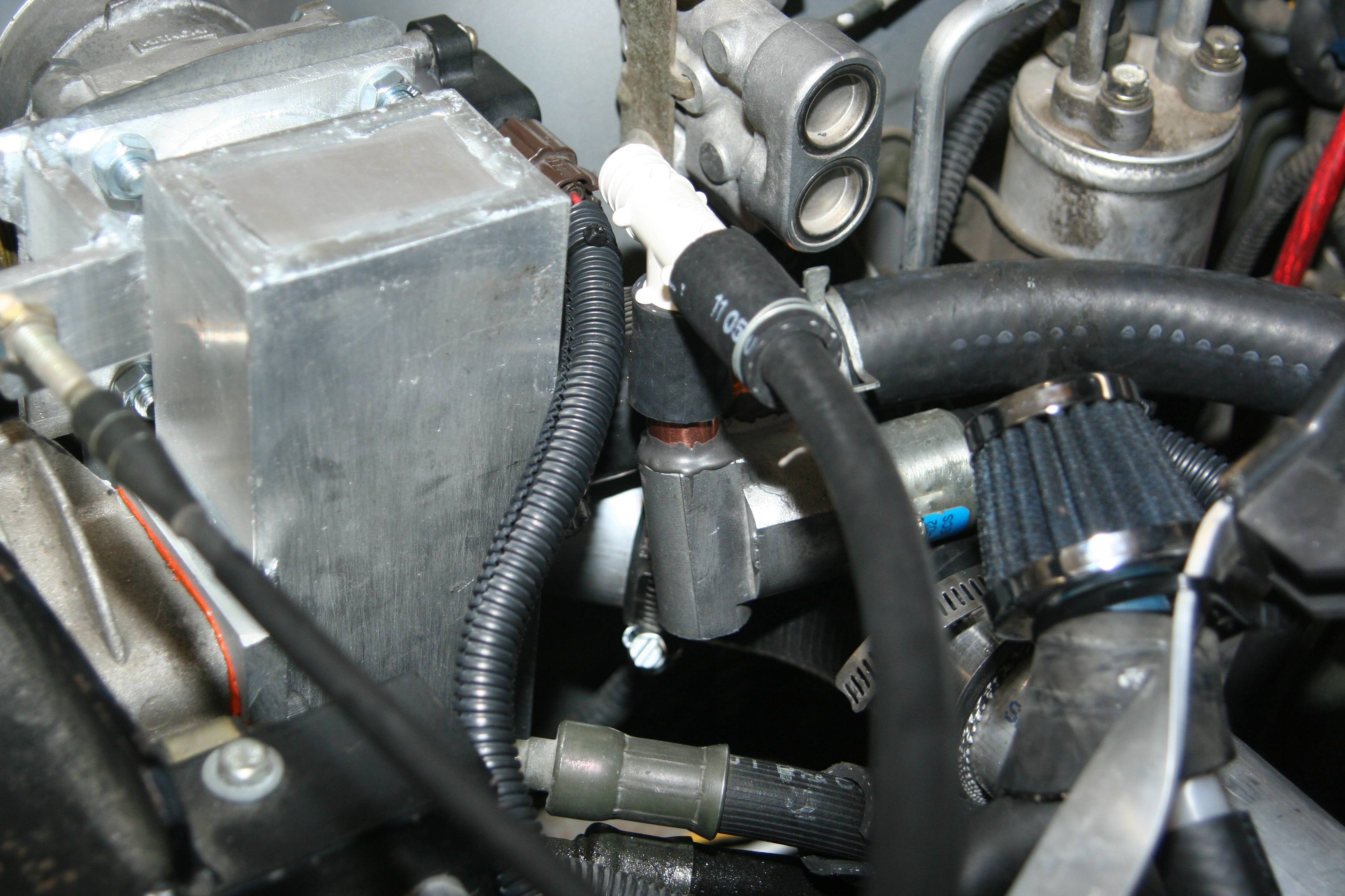
The IAC is installed with one end of the copper T fitting coupled to the 1"OD aluminum tube sticking out the back of the intake box. You know, that tube that is also used to feed the mounting bolt through. The other end of the T is currently capped off. In the above photo, there is a large piece of 1"ID rubber hose running off the other side of the T fitting and to the right of the photo. This was my initial attempt to use my Forge BOV as a CBV in this configuration. Something that didn't, and doesn't work. It's not there any more. One day I might try to add a proper Supercharger CBV, but until then it remains capped.
Sticking up from the IAC valve, and connected with a short piece of rubber hose, is the air feed for the Idle Air. Air is sucked in through that hose, and allowed into the intake box through the copper T fitting. The white plastic T fitting you see above the IACV is where the fresh filtered air will come from. The hose running towards me in the photo is the Air Assist Solenoid feed hose. Because I still have my stock injectors, and their Air Assist plumbing, I also needed to keep feeding fresh air to the solenoid. The other side of the plastic T is plumbed into the 90deg silicone elbow. Again, this side of the IACV and Air Assist only needs filtered air sourced from in FRONT of the Throttle Body.
Cables and Wires
The routing of the throttle cable was easy. It is the perfect length to bend across and secure to the new mounting tab. No need to extend or anything. My Cruise control cable is still left on the original TB. That is until I one day find a way to connect it to the new TB.
The IAC and TPS wires had to be extended too. Not by a lot, but a bit. I shouldn't have to describe how to do that. If you need a guide showing how I extend some wires, then I don't think you should be attempting to duplicate my build either. Actually, now that I think about it, I seem to recall that the IACV plug was just long enough. I unwrapped it from the factory loom, and managed to pull out enough wire to reach. But, it's a snug reach.
All Put Together
The new TB location, and it's even running! Note, the Forge BOV is still there. This was before I learned that I couldn't use it. Didn't take long to figure it out though.
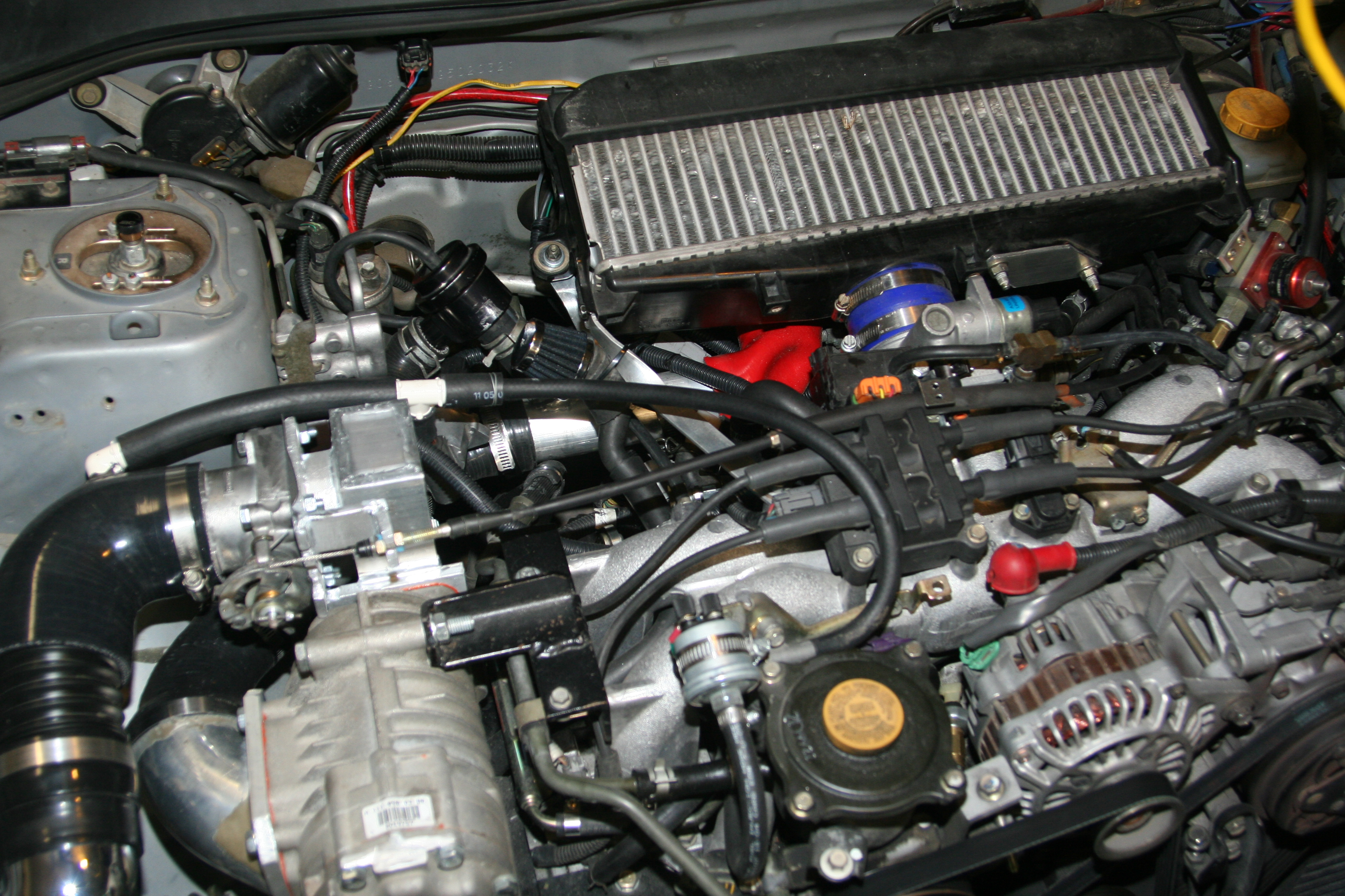
Above you can see it installed, and running! Notice the red Y-Pipe has a dimple in it? That's how I know it's running. Because the Silicone can't handle vacuum. See below for more on the Vacuum issue. Also, in that photo you can see that my Forge CBV is installed. This was before I learned/realized that it wouldn't work. It's not there any more.
A 3"ID to 2.75"ID Silicone Elbow connects the Filter tube to the TB inlet. A small white plastic 90deg elbow is JBWelded into the silicone elbow to feed filtered air to the IACV and Air Assist Solenoid. Don't forget to cap off the Air Assist port on the TB still attached to the intake manifold.
Run the throttle cable, the sensor wires, connect the hoses and fittings, and she started right up!!
The OEM TB is still there?
Yep, you see correctly. The original TB is still in place. But, it's basically disabled. I had a 2nd TPS, and IAC solenoid, so I didn't need to worry about removing my old ones. They stay in place, and are just left unplugged. The linkage is still there also. I just reached in the opening with a screw-driver and removed the round butterfly plate. And voila! One fully dis-functional Throttle Body. It's just used to I didn't have to build some sort of Intake->Intercooler mount.
No More CBV?
That's right, no more CBV with this setup. There are 2 reasons for this. * The type of CBV (just a BOV with a light spring) doesn't work with a proper draw through system. Only a standard CBV that uses a butterfly valve an correctly work in this configuration. It's hard to explain, and harder to visualize, but trust me when I say it doesn't work. it has to do with the forces of boost and vac working on different faces at the same time. * With only 5psi, there really is no need for a CBV. A CBV is used to relieve the added load on the engine during high vacuum cruising or idle situation. But, with a system that only makes 5psi of boost, the added load is very very low. In fact, I've not noticed a single difference in my MPG. Think about the old BB Chevys and Fords with 671 blowers on them. They didn't typically use a CBV either. This fact is also confirmed in numerous Supercharger books. So, don't worry about not using one.
Oops, Silicon couplers and Vacuum
Yep, This is a big fail on my part! I didn't even anticipate it. Oops! While not stopping my motor from running, it's not ideal. The silicon couplers are ok since they have a tiny exposed gap between the pipes. But the elbows and long runs can't stand up to the 20inHg of vacuum created at idle.
You can see the Silicone Y-Pipe collapsing under idle Vac
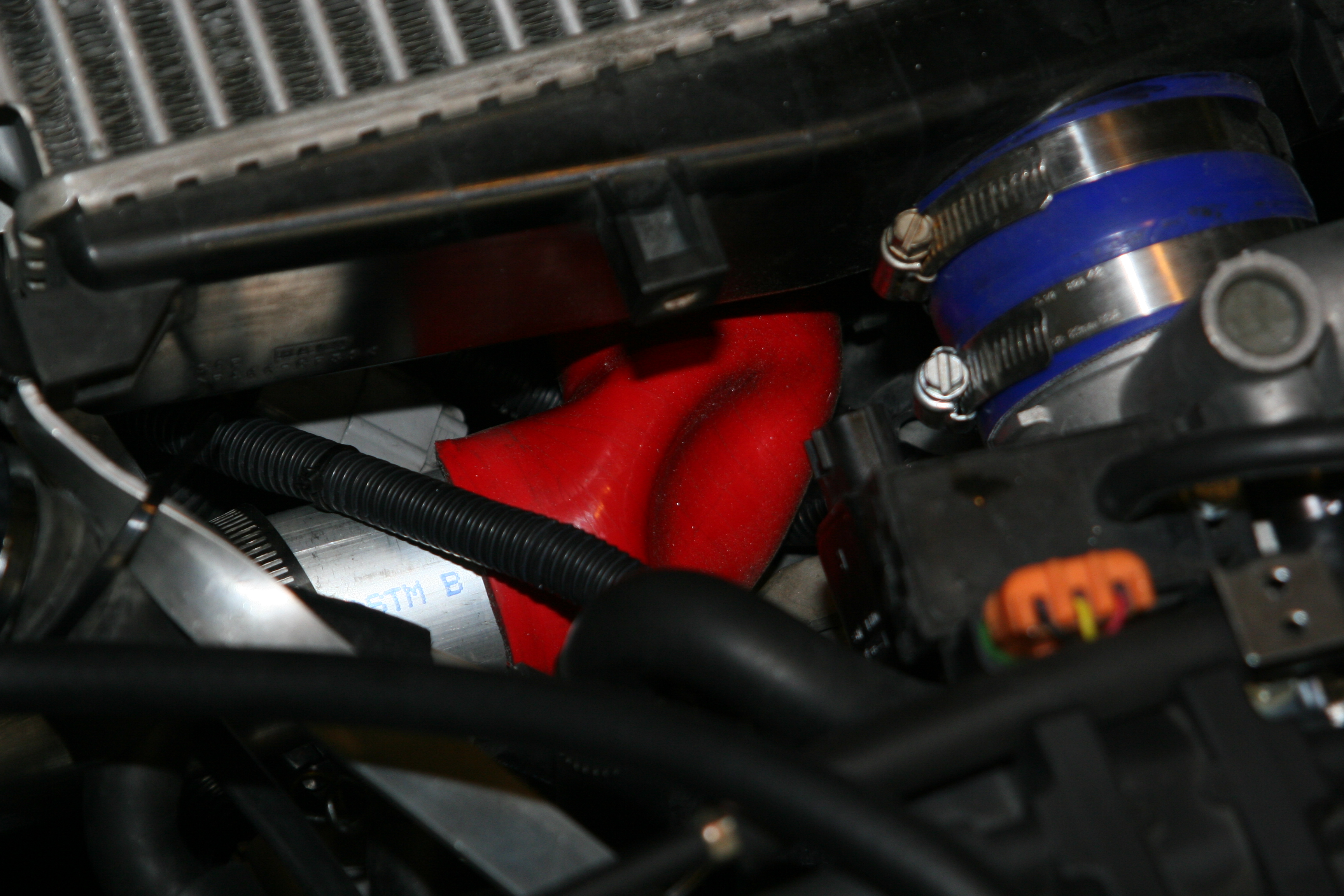
I'll be replacing as many of the elbows as I can with solid aluminum pieces. For now, I re-enforced the elbows by inserting short aluminum rings (cut from aluminum tube) inside the silicone part where it collapses. I used some sheet metal screws to ensure they hold in place. This is a temporary fix that is holding up just fine for now.
Before and After
Here is a Youtube Video of me at an AutoX in 2009 with the Throttle Body still in the stock location. You can see and hear that it performs fine, but is really loud.
And here is a YouTube video of me at an AutoX this year 2010 with the new Throttle Body Location
I think the videos speak for themselves.
Stay Tuned for Part 8, as I do away with the silicone elbows.